Handy mop

Inactive Publication Date: 2010-06-22
UNI CHARM CORP
View PDF100 Cites 11 Cited by
  • Summary
  • Abstract
  • Description
  • Claims
  • Application Information

AI Technical Summary

Benefits of technology

[0007]The present invention has been worked out in view of the shortcoming in the prior art set forth above. It is therefore an object of the present invention to provide a handy

Problems solved by technology

However, such means for preventing detachment of the mop body during use causes trouble in attachment and detachment of the mop body.
In addition, since the attachment por

Method used


Image

  • Handy mop
  • Handy mop
  • Handy mop

Examples


Embodiment Construction

[0021]The present invention will be discussed hereinafter in detail in terms of the preferred embodiment of a handy mop according to the present invention with reference to the accompanying drawings. In the following description, numerous specific details are set forth in order to provide a thorough understanding of the present invention. It will be obvious, however, to those skilled in the art that the present invention may be practiced without these specific details. In other instance, well-known structures are not shown in detail in order to avoid unnecessary obscurity of the present invention.

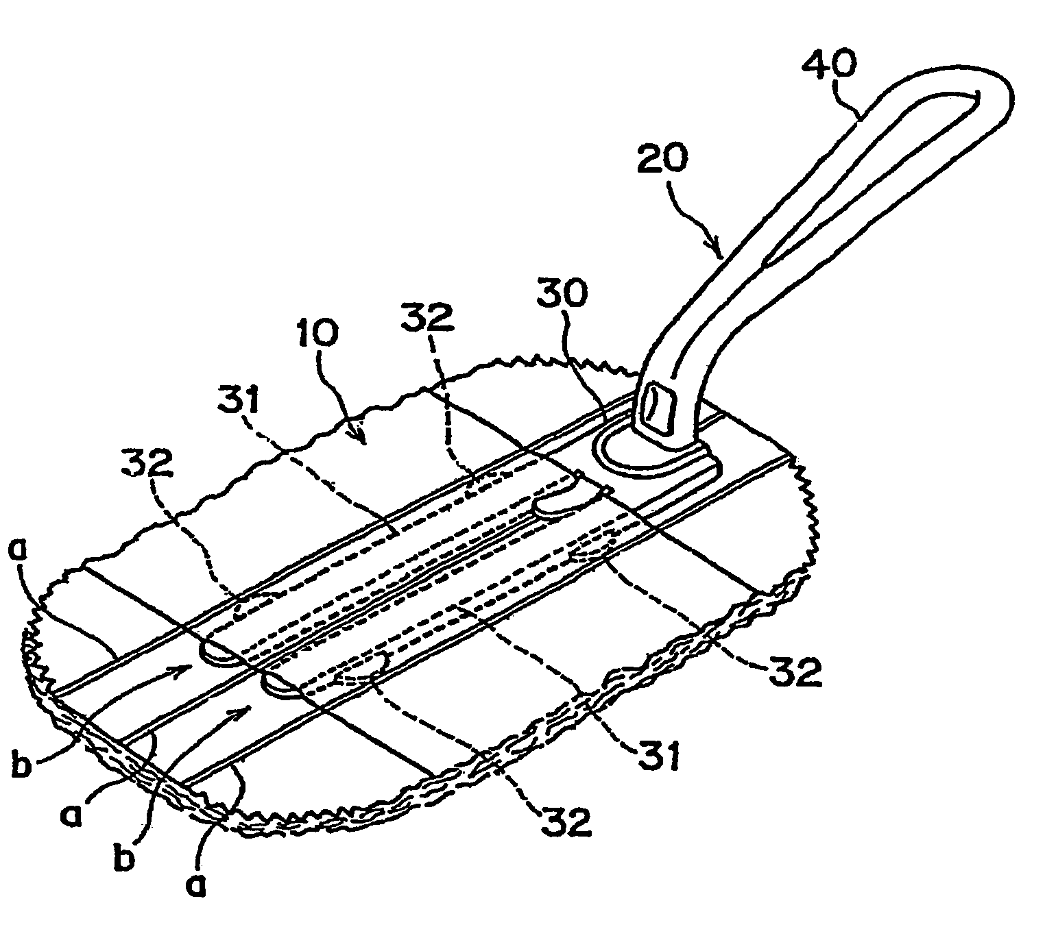
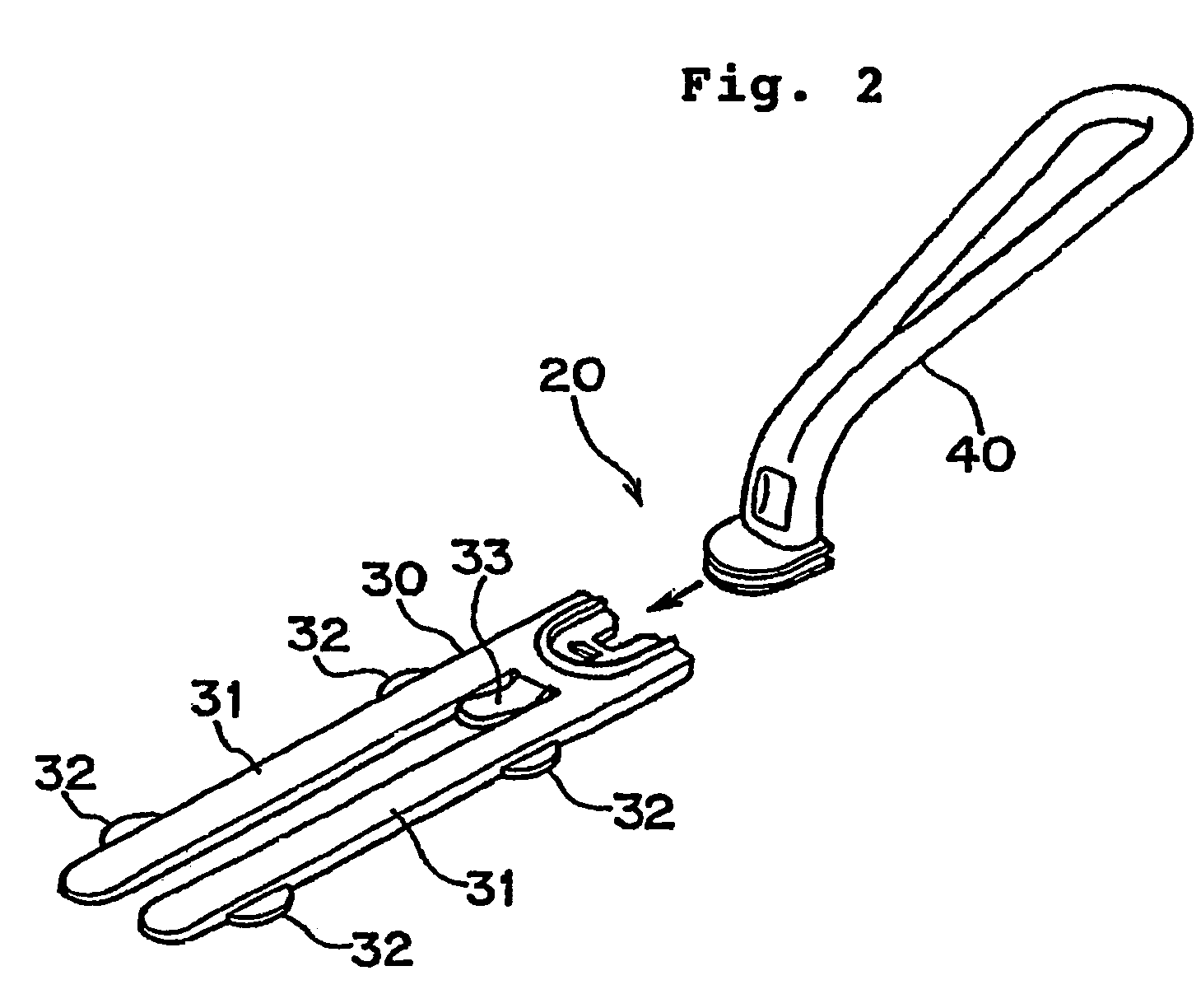
[0022]FIG. 1 is a perspective view showing a handy mop according to one embodiment of the present invention. The handy mop shown in FIG. 1 is composed of a mop body 10 and a handle 20 to which the mop body 10 is to be attached.

[0023]The mop body 10 comprises two or three fluffed nonwoven fabrics made of synthetic resin, which are stacked one on another and are then welded on lines extending...


PUM

PropertyMeasurementUnit
Lengthaaaaaaaaaa
Thicknessaaaaaaaaaa
Forceaaaaaaaaaa

Abstract

Disclosed is a handy mop including a mop body for collecting dust and a handle to which the mop body is to be attached. The mop body is provided with two gaps (b) extending in parallel for attachment of the handle thereto. The handle is provided with an attachment portion and a gripper extending rearwardly upwardly from a root end of the attachment portion. The attachment portion is bifurcated at the root end to provide two insert plates, which are flat and level, and are to be inserted into the gaps (b) of the mop body for use.

Description

CROSS REFERENCE TO THE PRIOR APPLICATION[0001]This is a U.S. national phase application under 35 U.S.C. §371 of International Patent Application No. PCT / JP01 / 09377, filed Oct. 25, 2001, and claims the benefit of Japanese Patent Application No. 2000-328865, filed Oct. 27, 2000 and Japanese Application No. 2001-317660, filed Oct. 16, 2001. The International Application was published in English on May 2, 2002 as WO 02 / 34101 Al under PCT Article 21(2).BACKGROUND OF THE INVENTION[0002]1. Field of the Invention[0003]The present invention relates to a handy mop which can be used for cleaning operation to remove dust in a room, car or the like.[0004]2. Description of the Related Art[0005]The handy mop of this type is generally constructed by attaching a mop body to a handle for use. Such a mop body used to be of a reusable type that can be washed after stained. However, in recent years, a disposable type of mop body has become to be widely used in combination with a handle to which the disp...

Claims


Application Information

Patent Timeline
IPC IPC(8): A47L13/20A47L13/24A47L13/254A47L13/38B25G3/18
CPCA47L13/20A47L13/24A47L13/38A47L13/46B25G3/18
Inventor TANAKA, YOSHINORIHAYASHI, MASAHOUENISHI, TOSHIHIKO
Owner UNI CHARM CORP
Why Eureka
Try Eureka