Telescoping boom for excavating apparatus

a technology of telescopic booms and excavating equipment, which is applied in the direction of excavations, lifting devices, constructions, etc., can solve the problems of slow operation of outer booms, too slow work to be efficient for various tasks, and difficult control of joint booms for grading purposes, etc., to achieve the effect of improving the length of couplings

Inactive Publication Date: 2010-06-22
BEATON ERIC
View PDF7 Cites 3 Cited by
  • Summary
  • Abstract
  • Description
  • Claims
  • Application Information

AI Technical Summary

Benefits of technology

[0012]It is an object of the present invention to improve the construction industry and, more particularly to improve the art of excavation.
[0013]It is another object of the present invention to improve the rate at which grading surfaces is conducted.
[0015]It is still another object of the present invention to provide a telescoping boom that extends and retracts faster than the telescoping boom of the prior art.
[0025]A second hydraulic cylinder can be used to connect the lever segment with the outer boom. For additional length, the piston of the second hydraulic cylinder is couple to a linkage to improve the length of the coupling between the lever segment and the outer boom.
[0026]Thus, for increased speed the second hydraulic cylinder also extends and retracts the outer boom.

Problems solved by technology

However, the jointed boom is rather difficult to control for grading purposes.
The main problem with this telescoping boom is that it works too slow to be efficient for various tasks.
Thus, the operation of the outer boom is slow.
Further, and more importantly, a large amount of hydraulic fluid must be moved to force the movement of the within cylinder.
Moving such large amount of hydraulic fluid repeatedly during strokes builds up heat.
The built up heat wears out the hydraulic cylinder and causes the hydraulic fluid lines to develop cracks.

Method used


Image

  • Telescoping boom for excavating apparatus
  • Telescoping boom for excavating apparatus
  • Telescoping boom for excavating apparatus

Examples


Embodiment Construction

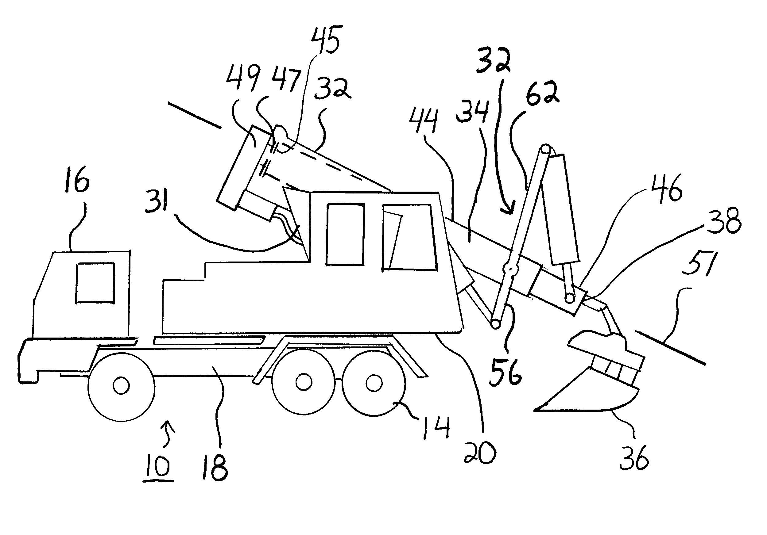
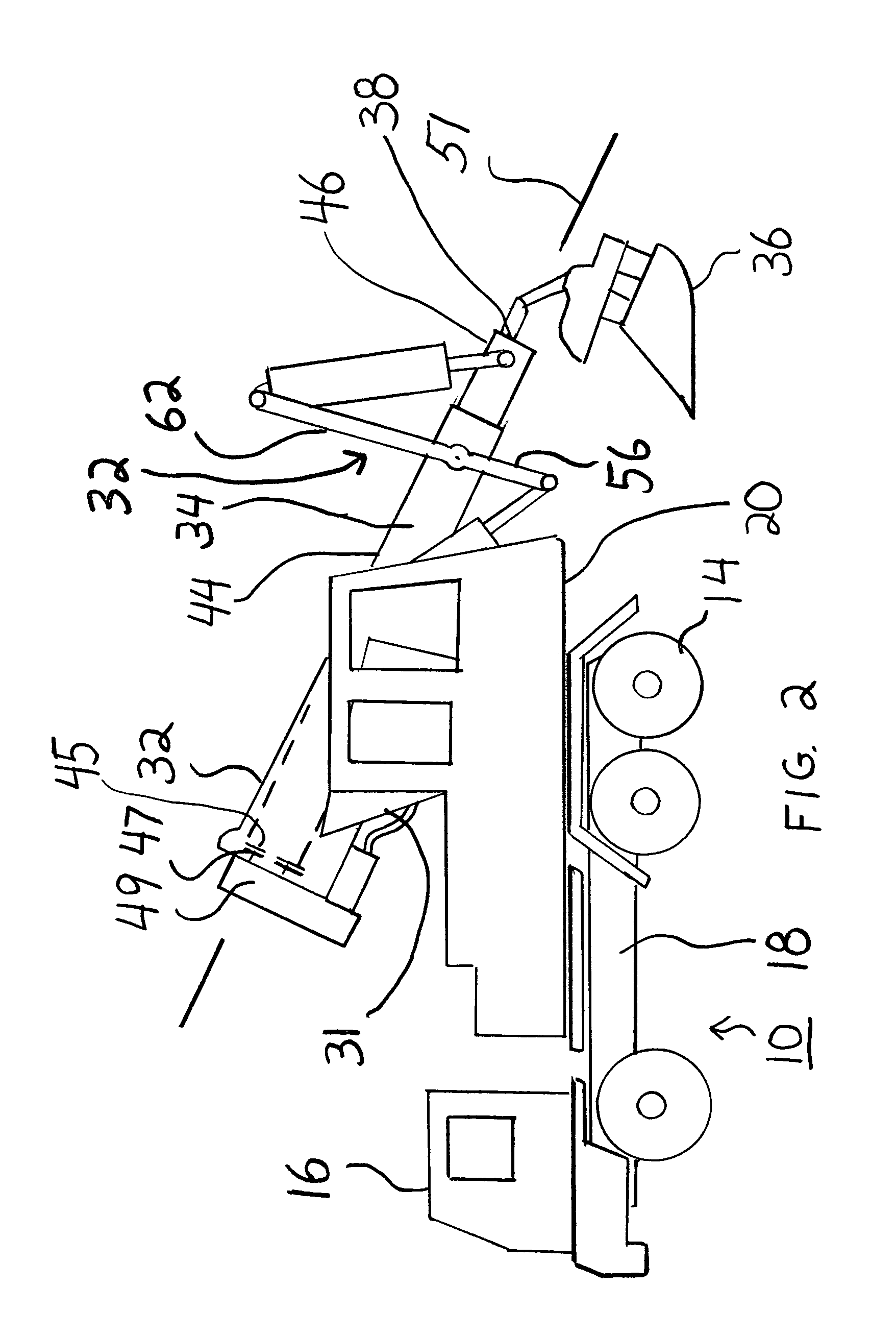
[0040]The present invention will now be described in accordance with the drawings. Referring now to FIG. 2, there is shown an excavation vehicle 10 in accordance with present invention. The excavation vehicle 10 includes a set of wheel tracks 12, depicted in FIG. 3, which allow the excavation vehicle to maneuver over various types of excavation surfaces. The excavation vehicle 10 may also include wheels 14 rather than wheel tracks. The wheel tracks 12 and wheels 14 are known in the art and need not be described herein.

[0041]A vehicle driving station 16 is used to take the excavation vehicle 10 to and from a work site. The vehicle driving station 16 is connected to the vehicle mainframe 18, also referred to herein as the vehicle base 18.

[0042]A rotating operating platform 20 rotates on a fulcrum 22, shown in FIG. 5, which is connected to the vehicle base 18. The rotating operating platform 20 includes a seating position 24 in which an operator controls all of the excavation features ...


PUM


Abstract

There is provided a telescoping boom system for an excavating apparatus which includes a linkage member having a pivot segment and lever segment pivoted about a rotating fixed boom. A first hydraulic cylinder is coupled from the fixed boom to the pivot segment. A second hydraulic cylinder is coupled from the lever segment to a retractable outer boom. The first hydraulic cylinder extends to rotate the pivot segment away from a proximate end of the fixed boom, thus forcing the lever segment to rotate towards the proximate end of the fixed boom. The second hydraulic cylinder retracts and combines with the extension force of the first hydraulic cylinder across the linkage member to provide a retraction force to the outer boom.

Description

FIELD OF THE INVENTION[0001]The present invention relates generally to the field of excavation apparatuses and, more particularly, to a telescoping boom for an excavation apparatus.BACKGROUND OF THE PRESENT INVENTION[0002]In the construction industry, it is often necessary to grade a surface for various reasons, such as paving, installing walkways, landscaping etc. It is also necessary to dig holes for foundations, basements, swimming pools and the like. Excavation which includes digging and grading is accomplished via an operating implement, such as a grading bucket, digging bucket, grapple, hammer, screening bucket etc., which is disposed at the outer end of a telescoping boom or a jointed boom.[0003]Excavation using a jointed boom is accomplished via a backhoe. The jointed boom works well for digging because the jointed boom operates at a quick speed. However, the jointed boom is rather difficult to control for grading purposes. Thus, a separate bulldozer must be brought on site ...

Claims


Application Information

Patent Timeline
Patent Type & Authority Patents(United States)
IPC IPC(8): E02F3/32
CPCE02F3/286B66C23/701
Inventor BEATON, ERIC
Owner BEATON ERIC
Why Eureka
Try Eureka