

Method and apparatus for pulsed L.E.D. illumination for a camera
a technology of pulsed illumination and camera, applied in the field of lighting, can solve the problems of reducing light output, dimming light, and corresponding power loss in the resistor, and achieve the effect of low weigh
- Summary
- Abstract
- Description
- Claims
- Application Information
AI Technical Summary
Benefits of technology
Problems solved by technology
Method used
Image

Examples
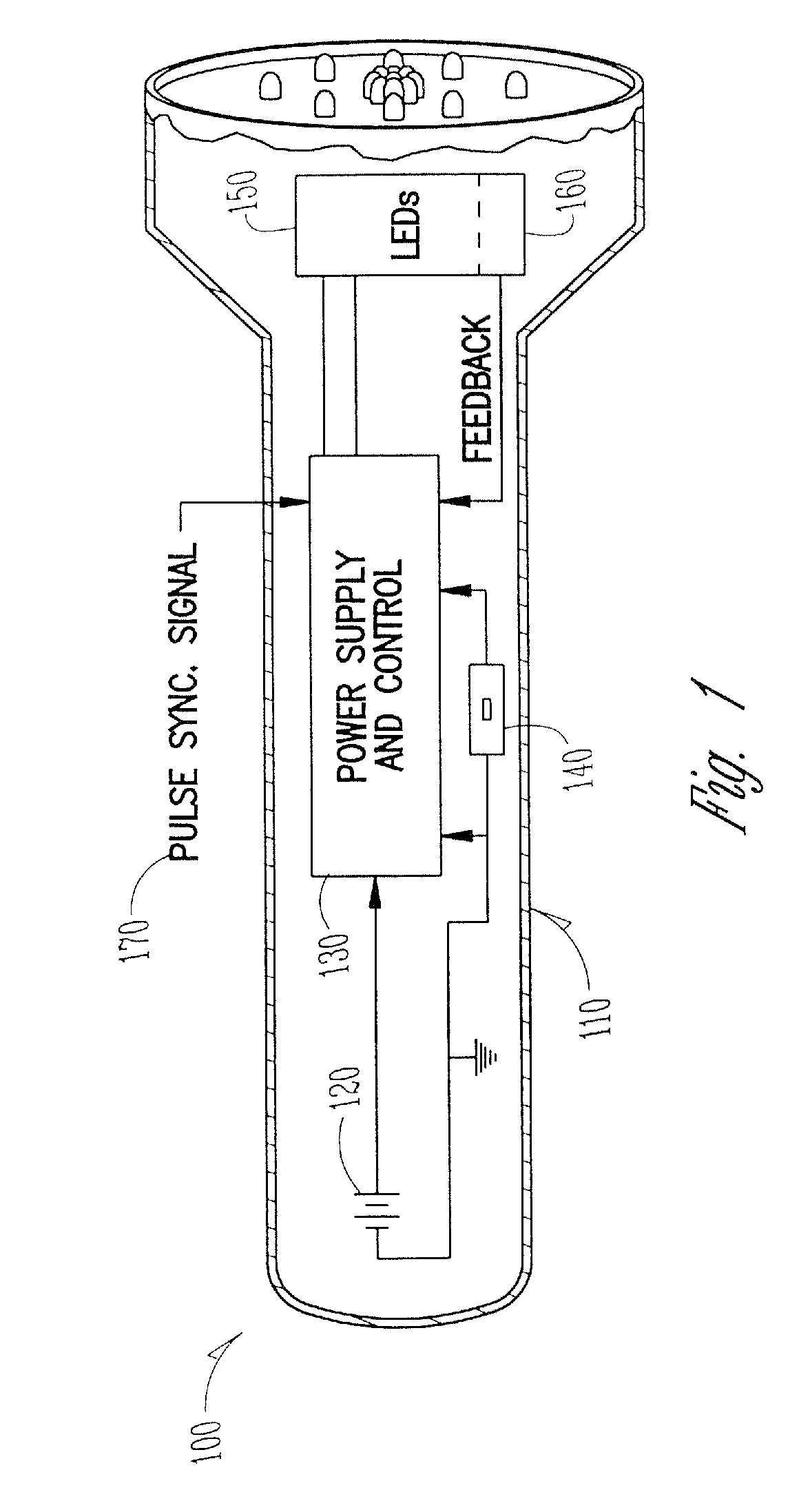
case 110
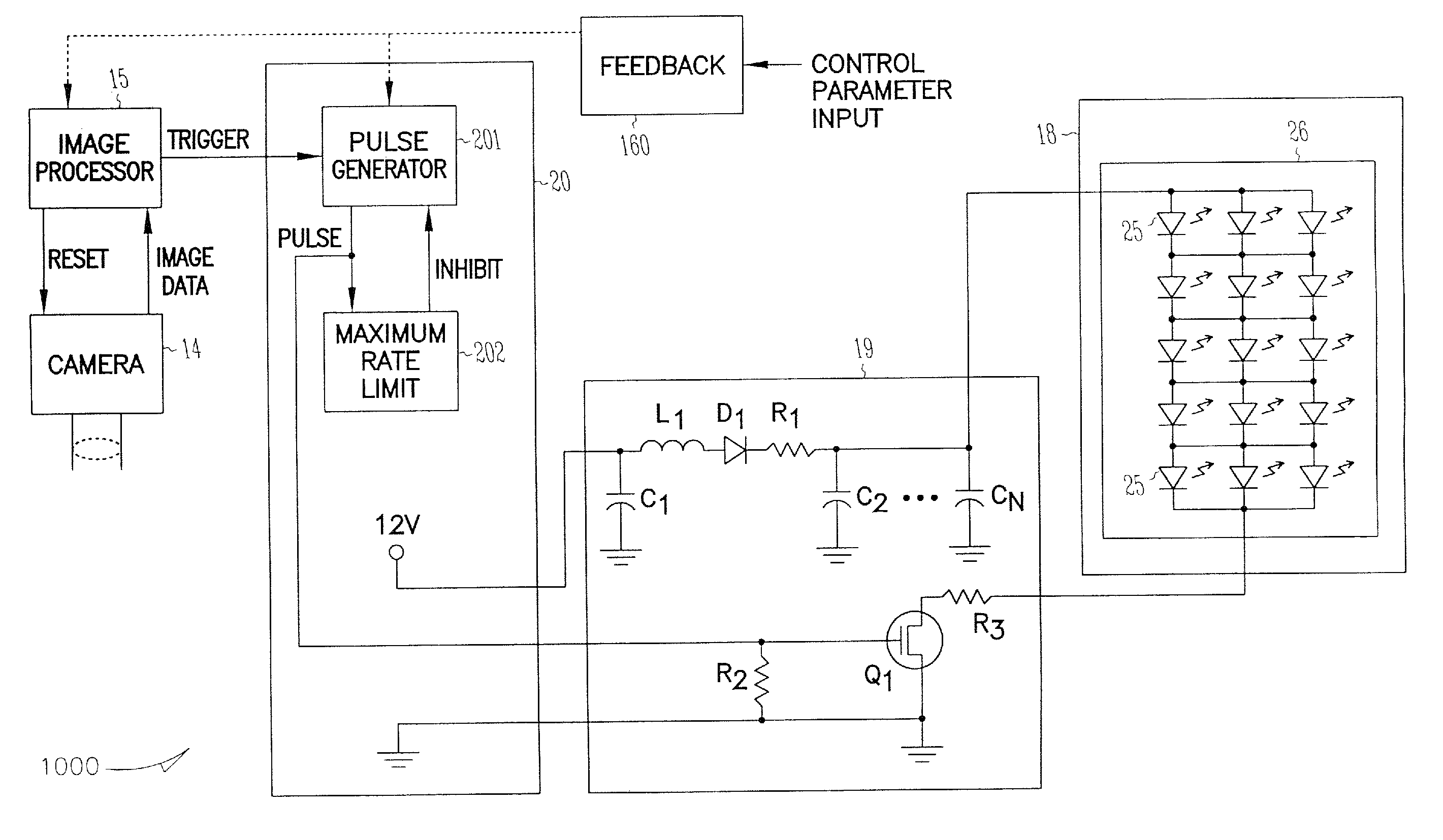
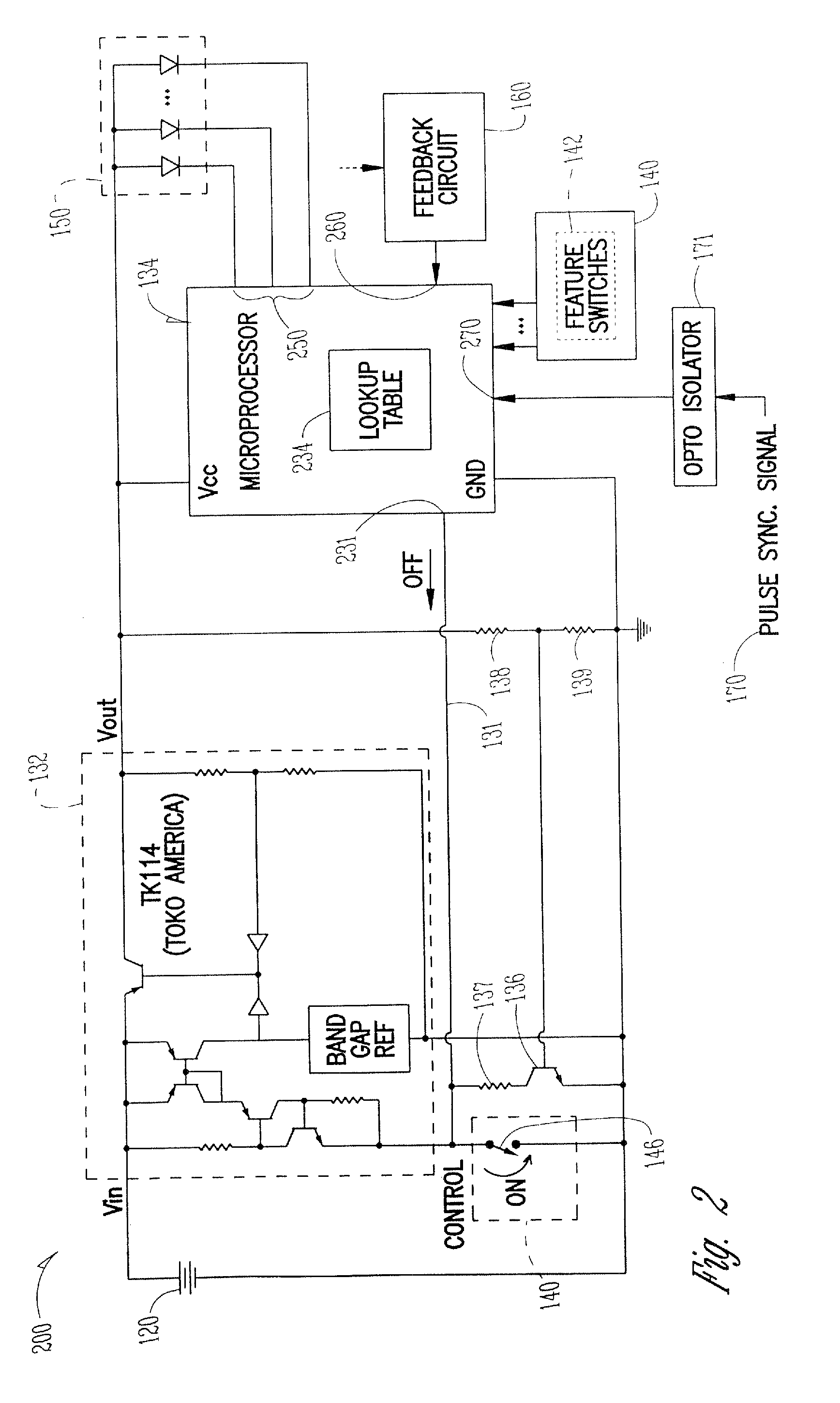
[0045]Case 110 is any convenient size and shape, and is typically designed to hold the battery, provide a suitable grip to be handheld, and provide a housing for the circuitry and LEDs. In one embodiment, battery 120 includes one or more cells which can be any suitable technology such as alkaline dry cells or rechargeable cells. Alternatively, other portable DC electrical power sources can be used as desired in place of battery 120. Power supply and control circuit (PSCC) 130 responds to switch circuit to apply electrical power from battery 120 to LEDs 150, controlled in order to prevent overloading and premature destruction of LEDs 150 while minimizing power dissipation within PSCC 130, thus maximizing battery life, providing the desired accuracy or level of the amount of light emitted at different battery voltages or other environmental conditions that would otherwise vary the light output. Switch circuit 140 allows the user to control various flashlight functions such as, for exa...
PUM
 Abstract
Description
Claims
Application Information