Laser induced liquid jet generating apparatus

a technology of laser, which is applied in the field of laser induced liquid jet generating apparatus, can solve the problems of reducing the efficiency of laser beam irradiation, limiting the intensity of laser beam, and difficult to recover from neuropathic symptoms, so as to reduce the burden on the human body and enhance the operating property

Inactive Publication Date: 2010-06-22
TERUMO KK
View PDF19 Cites 49 Cited by
  • Summary
  • Abstract
  • Description
  • Claims
  • Application Information

AI Technical Summary

Benefits of technology

[0012]This invention provides a laser induced liquid jet generating apparatus which is capable of inducing irradiation with as powerful laser beam as possible even in a slender catheter without being thermally affected by the laser beam, permitting protracted use as well, and enjoying a smooth operation.
[0013]This invention also provides a laser induced liquid jet generating apparatus which is capable of recovering the target object such as the thrombus which has been shattered by the liquid jet without adding to the burden imposed on the human body.
[0015]The apparatus contemplated by this invention shuns irradiation of a laser beam in a slender and narrow catheter, irradiates the laser beam in a large spatial part forming the interior of a main body, and introduces the generated liquid jet flow through a nozzle into a catheter. Consequently, it allows use of a slender catheter, avoids being thermally affected by the laser beam, attains irradiation of as powerful laser beam as possible, permits a protracted use, and realizes a smooth operation. As a result, it is capable of infallibly shattering the target object such as the thrombus very powerfully.
[0016]By injecting the liquid via the liquid injecting part toward the laser irradiating part of the optical fiber, it is made possible to exalt the effect of cooling the laser irradiating part of the optical fiber and add to the powerfulness with which the laser beam is irradiated.
[0019]Further, the apparatus allows one catheter to fulfill the function of shattering the target object and the function of recovering the shattered target object, attains the exaltation of the operating property, and brings the advantage of lessening the burden imposed on the human body as compared with the apparatus requiring provision of a separate tube.

Problems solved by technology

Particularly, when the cerebral tissue remains in the state of ischemia for not less than six hours, it is held that the restoration from the neuropathic symptom is difficult to attain.
Further, when it is used in the state of having an optical fiber inserted therein, it keeps the optical fiber itself from increasing its thickness, imposes a limit on the intensity of the laser beam, and renders irradiation of a powerful laser beam difficult.
The method, therefore, is possibly incapable of generating a powerful liquid jet flow and effecting necessary shattering of the target object such as the thrombosis, for example, sufficiently.
Since it is soft throughout the entire volume so as to be deformed along the meandering blood vessel, it tends to be thermally affected when it is exposed to a powerful laser beam.
When they are exposed to a powerful laser beam, the heat of the laser beam is conducted to the catheter and the catheter is consequently fused and deformed and made to obstruct smooth discharge of a liquid jet flow and curtail its own service life.
Further, since the catheter of this nature is only capable of shattering the target object such as the thrombus but is devoid of a means to recover the shattered target object, the thrombus which has been shattered is suffered to float in the blood vessel.
When these catheter and tube are inserted into the blood vessel, they bring the disadvantage of aggravating the burden imposed on the human body.

Method used


Image

  • Laser induced liquid jet generating apparatus
  • Laser induced liquid jet generating apparatus
  • Laser induced liquid jet generating apparatus

Examples


first embodiment

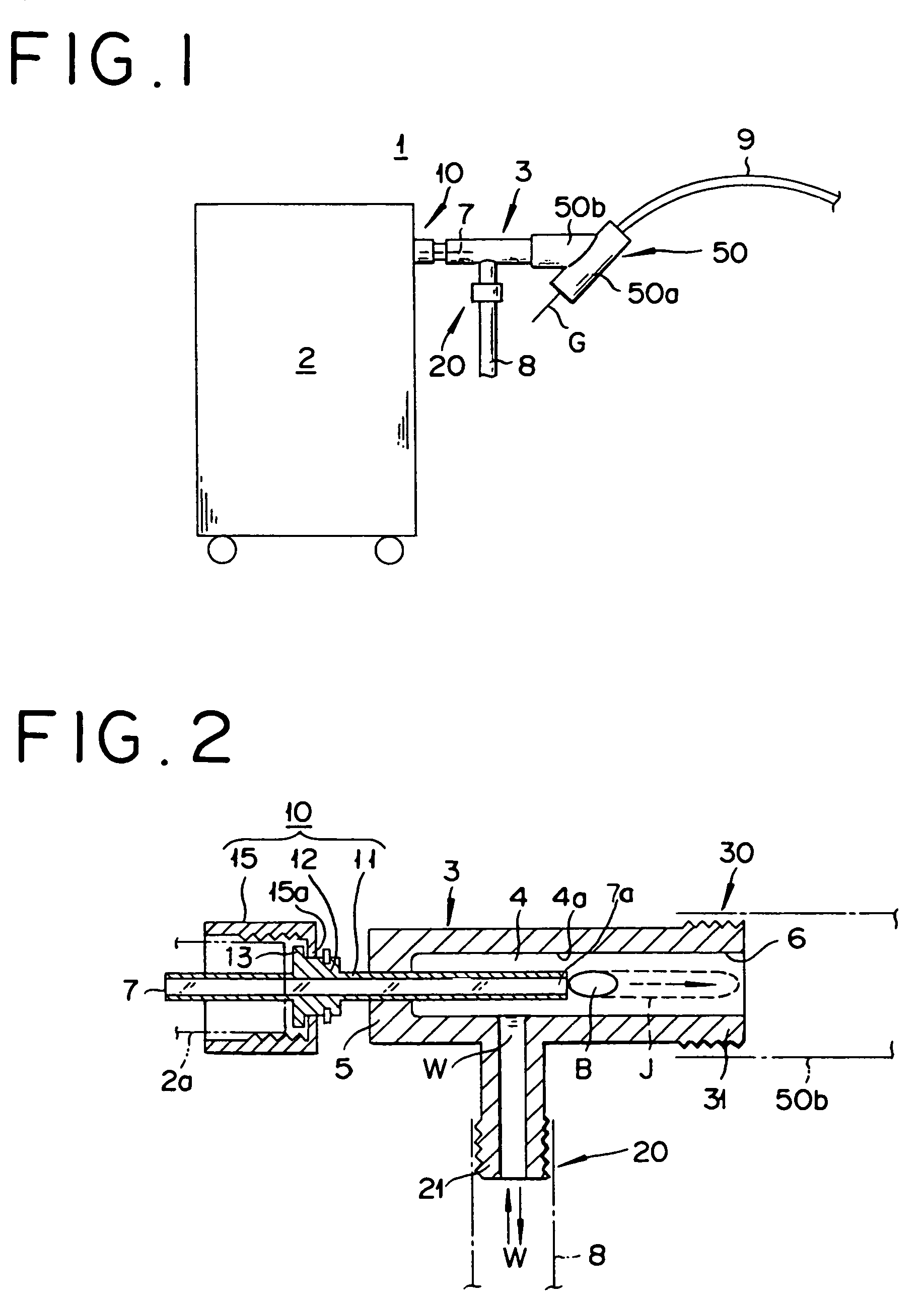
[0038]The first embodiment illustrated in FIG. 1 and FIG. 2 is a laser induced liquid jet generating apparatus 1 for curing the thrombosis which is a disease of forming a blood clot within a man's blood vessel. This apparatus 1 generally comprises a main body 3 connected to a laser oscillator 2, an optical fiber fitting part 10 made to communicate with the main body 3, a liquid injecting part 20 for injecting a prescribed liquid W into a spatial part 4 (refer to FIG. 2) of the main body 3, and a Y-shaped Y connector part 50 disposed at the leading terminal part (the leading terminal side of a ferrule 11) of the optical fiber fitting part 10.

[0039]Since the laser oscillator 2 is a thing well known already, the explanation thereof will be omitted. The main body 3 is a kind of coupler furnished with various members as shown in FIG. 2. The main body 3 is formed of a material possessing a high melting point enough to withstand the heat emitted by an optical fiber 7 together with stiffnes...

second embodiment

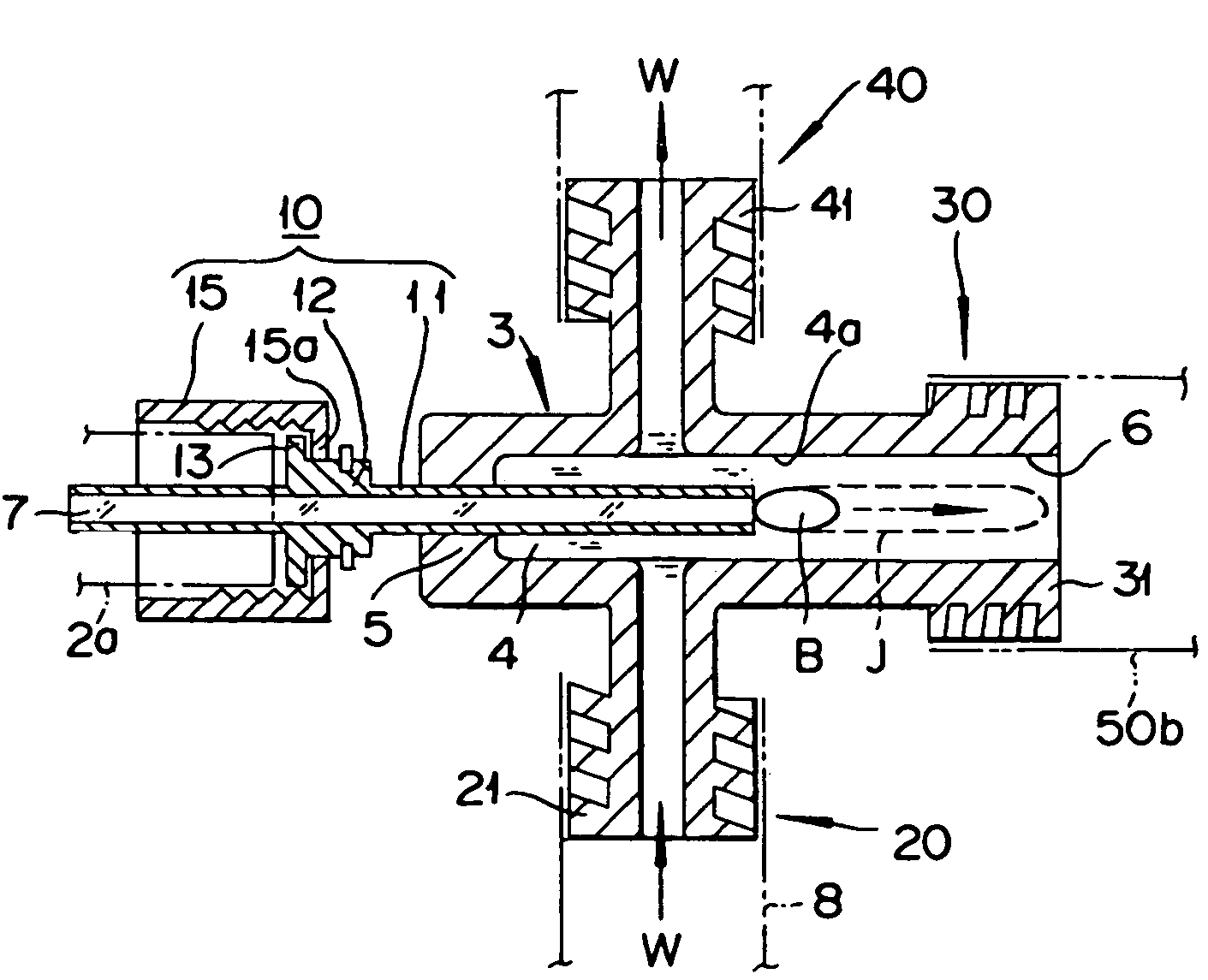
[0062]While the first embodiment utilizes the liquid injecting part 20 for extracting the shattered thrombus, the second embodiment illustrated in FIG. 4 contemplates generating a flow opposite the liquid jet flow, aspirating the shattered target substance from the distal end of the catheter 9, and removing it from within the blood vessel. Specifically, a liquid discharging part 40 is disposed opposite the liquid injecting part 20 of the main body 3 and it is utilized for generating the flow opposite the liquid jet flow. The same members as shown in FIG. 1 and FIG. 2 will be denoted here by the same reference numerals and their explanation will be omitted.

[0063]The liquid discharging part 40 is provided with a connecting part 41 having a screw tread formed in the terminal part thereof and is possessed of a passage in the interior thereof. It is connected to a suction pump, for example, through the medium of a hose. By the operation of this suction pump, it is enabled to discharge th...

third embodiment

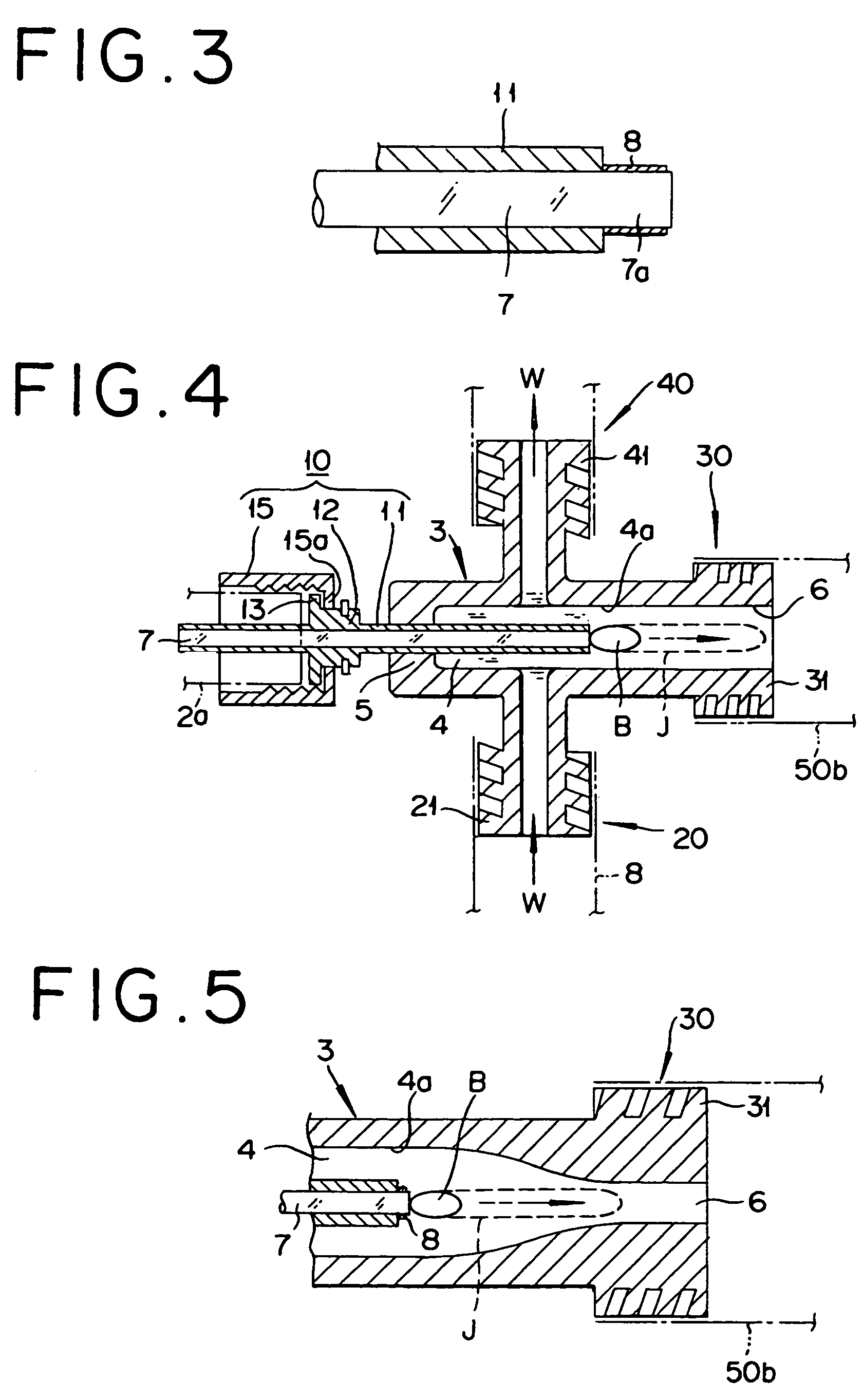
[0065]In the first and second embodiments, the spatial part 4 of the main body 3 has an inner wall surface 4a thereof formed nearly straight from the optical fiber fitting part 10 toward the nozzle 6. The inner wall surface 4a may be alternatively formed as tapered so that the inner diameter of the spatial part 4 decreases toward the leading terminal as shown in FIG. 5.

[0066]By thus tapering the inner wall surface 4a, the speed of flow of the liquid jet J induced by the laser irradiating part 7a is further heightened by the tapered spatial part 4 and the shattering is attained more powerfully. Moreover, when the spatial part 4 is in the tapered shape, it constitutes a guide and enables the power of the liquid jet flow to be smoothly introduced into the catheter 9.


PUM


Abstract

The laser induced liquid jet generating apparatus irradiates a laser beam on a liquid in a main body, guides the generated liquid jet into a catheter via a nozzle, and generates a flow in the direction opposite the liquid jet. Even by the use of a catheter having a small outside diameter, therefore, the apparatus is enabled to effect powerful laser irradiation without being thermally affected by the laser beam and consequently shatter thrombus, for example, and recover by aspiration the shattered thrombus through the distal end of the catheter.

Description

CROSS-REFERENCE TO RELATED APPLICATIONS[0001]This application is based upon Japanese Patent Applications No. 2003-392130 and No. 2003-392133 filed Nov. 21, 2003 the contents of which are hereby incorporated by reference.BACKGROUND OF THE INVENTION[0002]1. Field of the Invention[0003]This invention relates to a laser induced liquid jet generating apparatus which serves the purpose of irradiating a laser beam against a liquid thereby generating a liquid jet flow and utilizing the jet flow to shatter a target object such as thrombus, and recovering the shattered object.[0004]2. Description of the Related Art[0005]In recent years, as a means to cure the thrombosis which obstructs the human blood vessel, the method which consists in generating a liquid jet flow with a laser beam and physically breaking the clot with the jet flow is prevailing. This method has been awakening a great expectation for the therapy of the thrombosis because it promises early resumption of the blood flow withou...

Claims


Application Information

Patent Timeline
Patent Type & Authority Patents(United States)
IPC IPC(8): A61B18/20A61B17/32A61B18/26
CPCA61B18/26A61B17/3203A61B2018/263A61B2017/32032A61B17/32037
Inventor TAKAYAMA, KAZUYOSHIHIRANO, TAKAYUKINAKAGAWA, ATSUHIROOBITSU, HIDESHIOMORI, SHIGERUKANAMARU, TAKESHI
Owner TERUMO KK
Why Eureka
Try Eureka