
Exhaust gas purifying apparatus for internal combustion engine

a technology for exhaust gas purification and internal combustion engines, which is applied in mechanical equipment, machines/engines, electric control, etc., can solve the problems of significant deterioration of drivability and fuel consumption of internal combustion engines, and achieve the effect of preventing drivability deterioration

Inactive Publication Date: 2010-06-29
TOYOTA JIDOSHA KK
View PDF11 Cites 6 Cited by
  • Summary
  • Abstract
  • Description
  • Claims
  • Application Information

AI Technical Summary

Benefits of technology

This approach allows for effective regeneration of exhaust gas purifying units while preventing fuel consumption and drivability deterioration, even when regeneration control is executed, by synchronizing or adjusting regeneration based on combustion mode changes.

Problems solved by technology

For example, if the combustion modes of the banks are changed differently for the purpose of the regeneration control and the regeneration control is executed at the different timings, fuel consumption of the internal combustion engine and drivability may be significantly deteriorated.
However, in the exhaust gas purifying apparatuses according to the above-mentioned Reference-1 to Reference-3, since the regeneration control is independently executed for each bank even when the combustion mode is changed before and after the execution of the regeneration control, the drivability may be deteriorated.

Method used


Image

  • Exhaust gas purifying apparatus for internal combustion engine
  • Exhaust gas purifying apparatus for internal combustion engine
  • Exhaust gas purifying apparatus for internal combustion engine

Examples


first example

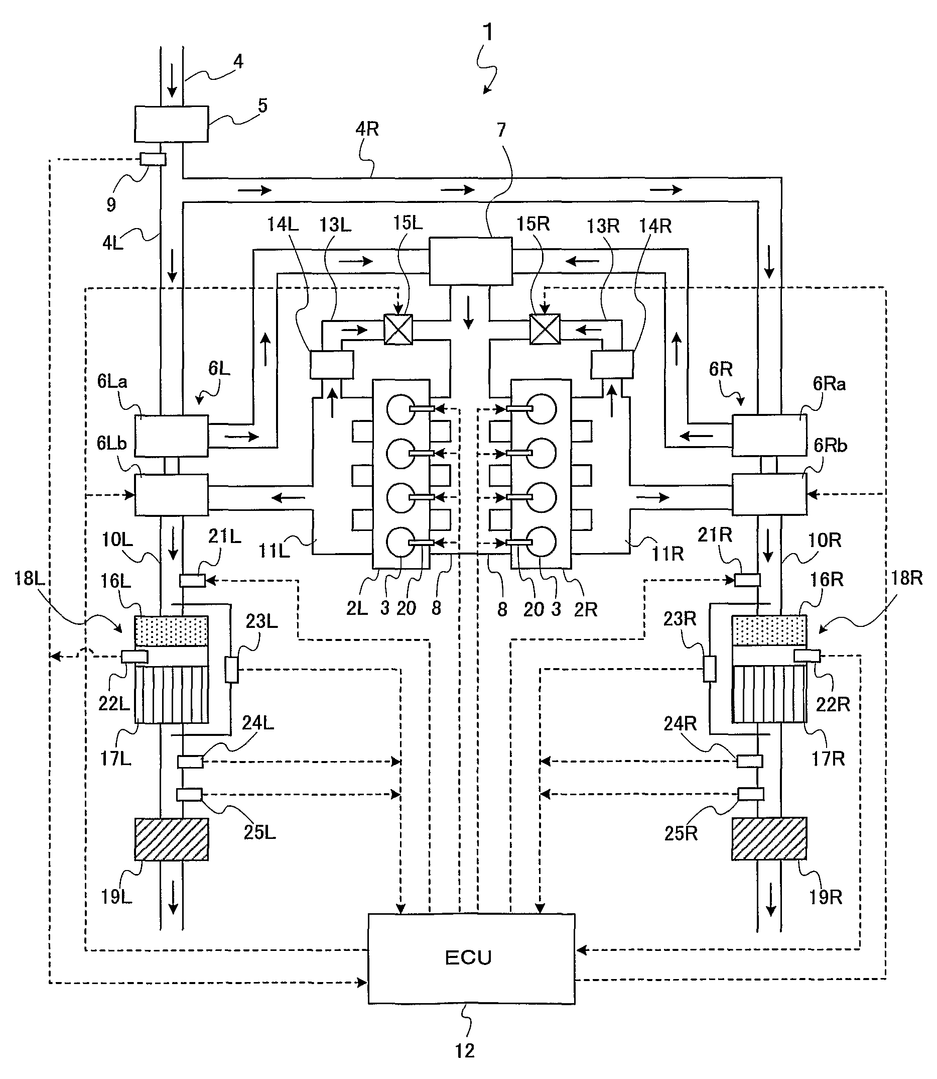
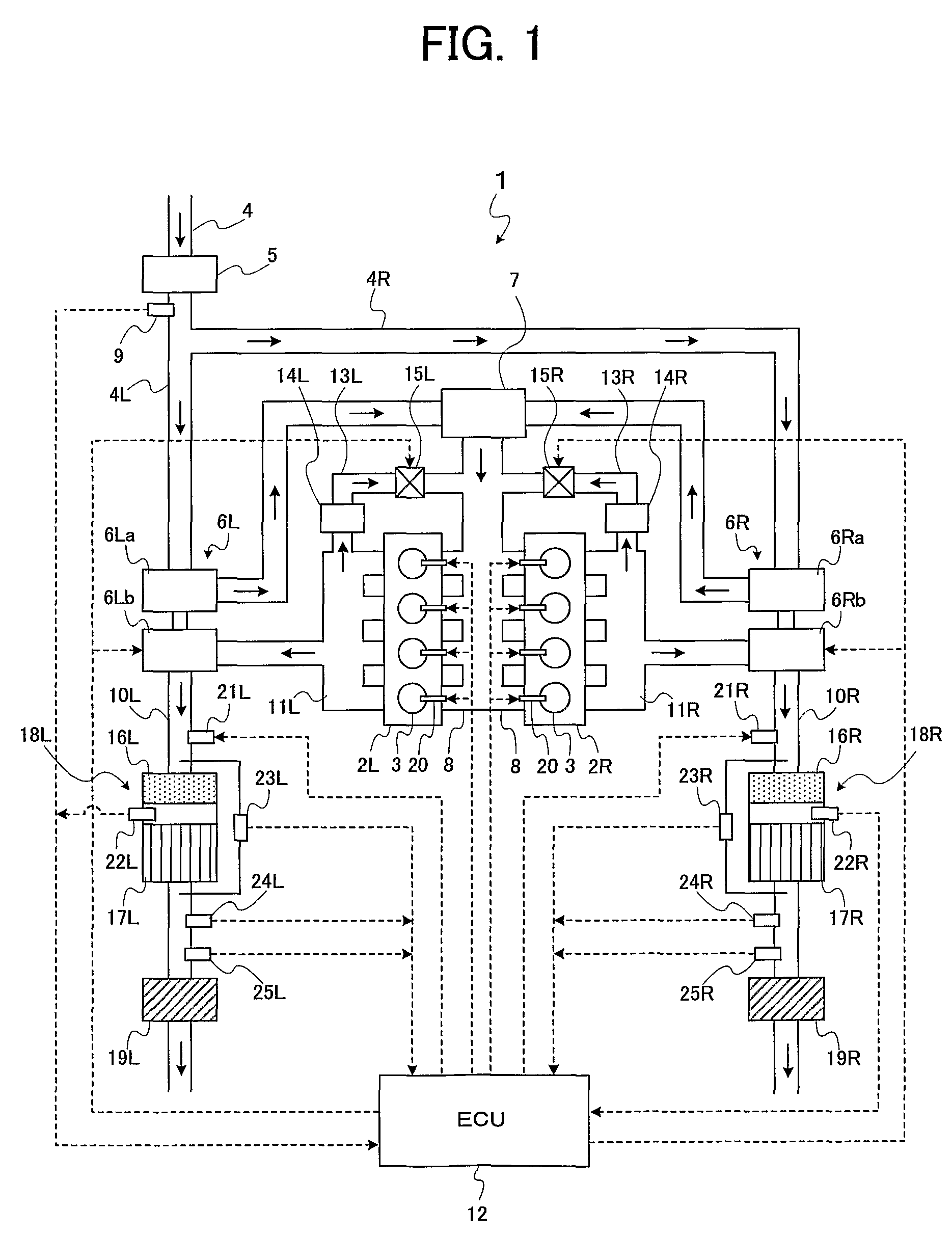
[0095]First, the regeneration control according to a first embodiment will be explained. The regeneration control according to the first embodiment is executed when the change of the combustion mode is involved. Thus, the control is simultaneously executed for the banks 2L and 2R. Moreover, the regeneration control according to the first embodiment is executed so that the PM regeneration in the banks 2L and 2R simultaneously end. Namely, the regeneration control is executed so that starts and ends of the control in the banks 2L and 2R coincide.

[0096]Concretely, based on the PM amount (hereinafter referred to as “estimated PM accumulation amount”) accumulated in the DPNRs 17L and 17R, the ECU 12 determines the fuel amount to be added per unit-time (hereinafter simply referred to as “fuel addition amount”) for each of the DPNRs 17L and 17R so that the time periods of executing the regeneration control become the same. Further, the ECU 12 also determines the time periods of executing t...

second embodiment

[0109]Next, a description will be given of the regeneration control according to a second embodiment. The regeneration control according to the second embodiment is also executed when the change of the combustion mode is involved, and hence the regeneration control is simultaneously executed for the banks 2L and 2R. Moreover, similarly to the regeneration control according to the first embodiment, the regeneration control according to the second embodiment is executed so that the PM regeneration simultaneously ends in the banks 2L and 2R.

[0110]The regeneration control according to the second embodiment is different from the regeneration control according to the first embodiment in that, not the fuel addition amount, but the exhaust gas amount supplied to the DPNRs 17L and 17R (i.e., the exhaust gas amount supplied per unit-time) is changed. Namely, changing the supplied exhaust gas amount makes the progressing speed of the PM regeneration in the DPNRs 17L and 17R different. Specific...

third embodiment

[0116]Next, a description will be given of the regeneration control according to a third embodiment.

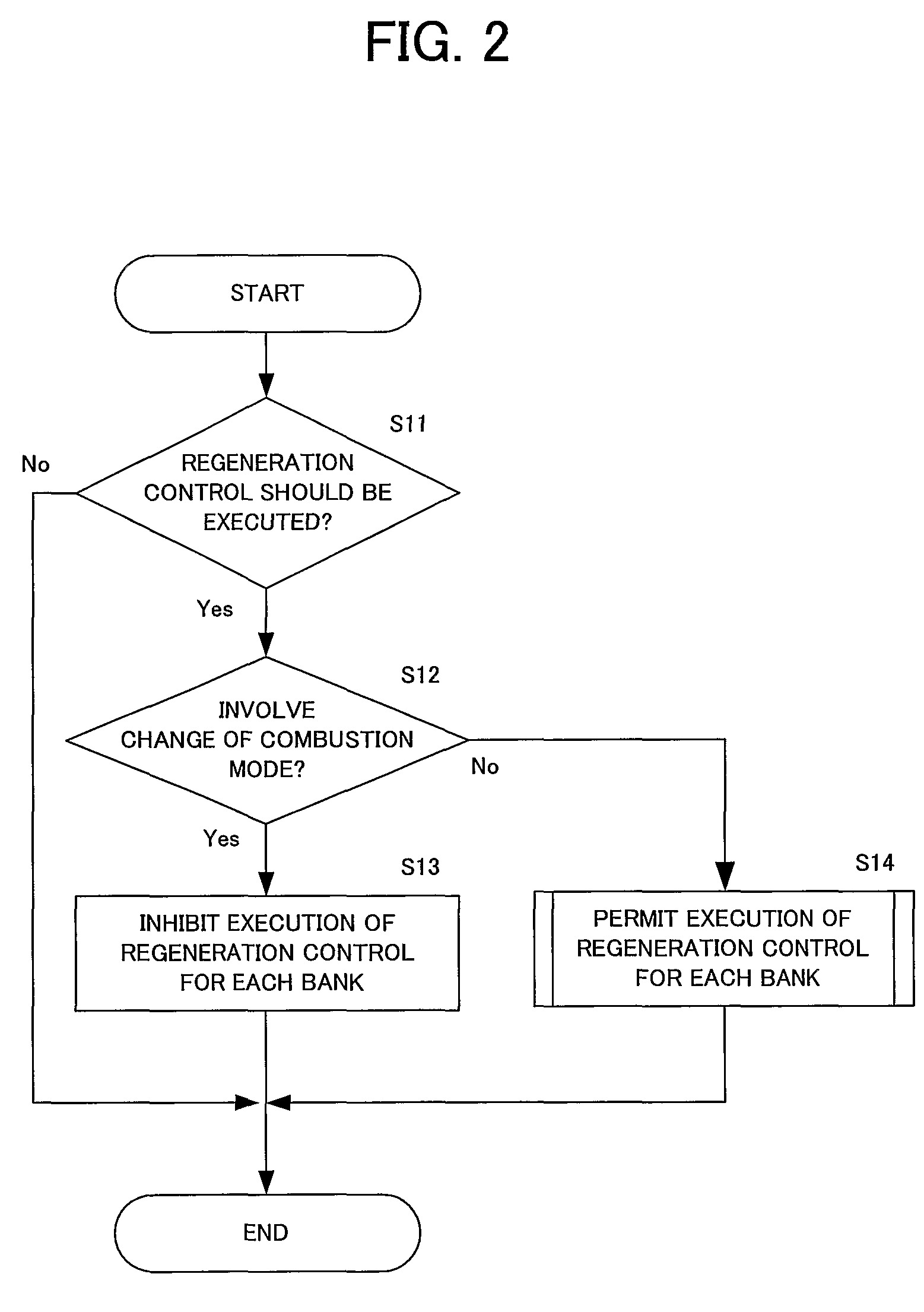
[0117]The regeneration control according to the third embodiment is different from the above-mentioned regeneration control according to the first and second embodiments. The regeneration control according to the third embodiment is executed in such a case that no change of the combustion mode is involved before and after the execution of the regeneration control. Concretely, in the third embodiment, the regeneration control simultaneously starts for the banks 2L and 2R, and the same fuel amount is added to the DPNRs 17L and 17R per unit-time. In this case, based on the estimated PM accumulation amount of each of the DPNRs 17L and 17R, the ECU 12 determines the time period for executing the regeneration control for each of them, respectively. Namely, during the determined time period, the ECU 12 executes the regeneration control for each of the DPNRs 17L and 17R. In this manner, the r...


PUM


Abstract

An exhaust gas purifying apparatus for an internal combustion engine includes plural exhaust gas purifying units which are provided on exhaust gas passages connected to plural cylinder groups in the internal combustion engine and purify exhaust gas flowing in the exhaust gas passages, a regeneration determining unit which determines whether or not the plural exhaust gas purifying units should be regenerated, and a regeneration control unit which executes regeneration control for regenerating the exhaust gas purifying units when the regeneration determining unit determines that the exhaust gas purifying units should be regenerated. The regeneration control unit simultaneously executes the regeneration control for the plural exhaust gas purifying units when a change of a combustion mode of the internal combustion engine is involved before and after execution of the regeneration control. Meanwhile, the regeneration control unit independently executes the regeneration control for each of the plural exhaust gas purifying units when the change of the combustion mode is not involved before and after the execution of the regeneration control.

Description

TECHNICAL FIELD[0001]The present invention relates to an exhaust gas purifying apparatus for an internal combustion engine.BACKGROUND ART[0002]As an internal combustion engine including plural groups of cylinders (banks) connected to different exhaust gas passages, there is known a V-type engine in which plural groups of cylinders are connected to different exhaust gas passages, respectively, for example. The internal combustion engine of this kind includes a catalyst and a filter for purifying exhaust gas in each of the exhaust gas passages.[0003]For example, Japanese Patent Application Laid-open under No. 11-117786 (Reference-1) discloses a technique, in which a SOx catalyst is provided for each exhaust gas passage connected to each bank and an air-fuel ratio is individually controlled for each bank so that the temperature of the SOx catalyst becomes a regenerating temperature at which the catalyst can be regenerated (activated). Thereby, regeneration control is executed. In addit...

Claims


Application Information

Patent Timeline
Patent Type & Authority Patents(United States)
IPC IPC(8): F01N3/00
CPCF01N3/0253F01N13/0097F01N3/0821F01N3/0885F01N9/00F02D41/0082F02D41/027F02D41/029F01N13/009F01N13/011F01N3/0807F01N13/107F01N2610/03F02B37/007F02B75/22F02D41/0065F02D41/10F02D41/40F02D2200/0812Y02T10/47Y02T10/40
Inventor OGISO, MAKOTO
Owner TOYOTA JIDOSHA KK
Learn More