Vertical pipe guard

a vertical and pipe guard technology, applied in the direction of machine supports, domestic objects, applications, etc., can solve the problems of rupturing of pipes, relatively labor-intensive installation process,

Active Publication Date: 2010-06-29
ARMACELL ENTERPRISE GMBH & CO KG
View PDF13 Cites 18 Cited by
  • Summary
  • Abstract
  • Description
  • Claims
  • Application Information

AI Technical Summary

Problems solved by technology

Initially, each pipe must be installed individually and as such the installation process is relatively labour intensive.
Secondly, the hangers can cause rupturing of the pipes after a period of time.
This would occur due to movement of the pipe within the pipe hanger and subsequent surface damage.

Method used


Image

  • Vertical pipe guard
  • Vertical pipe guard
  • Vertical pipe guard

Examples


Embodiment Construction

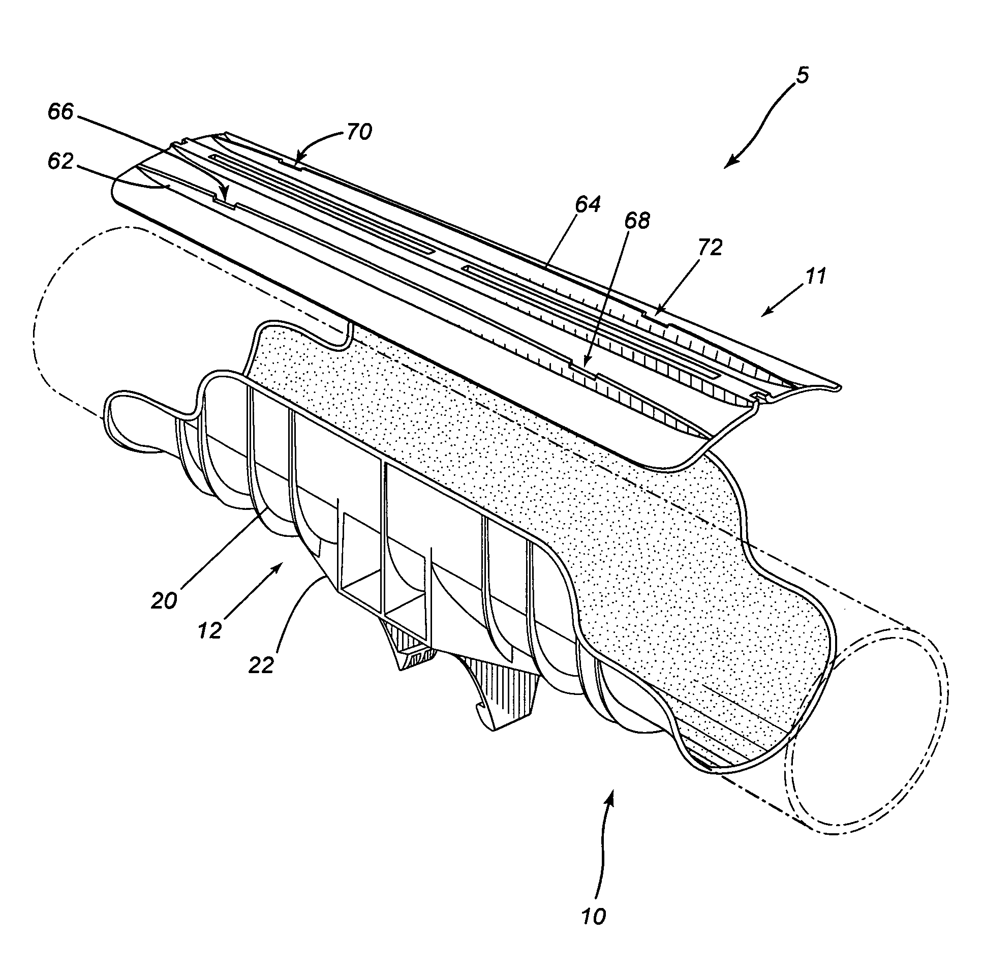
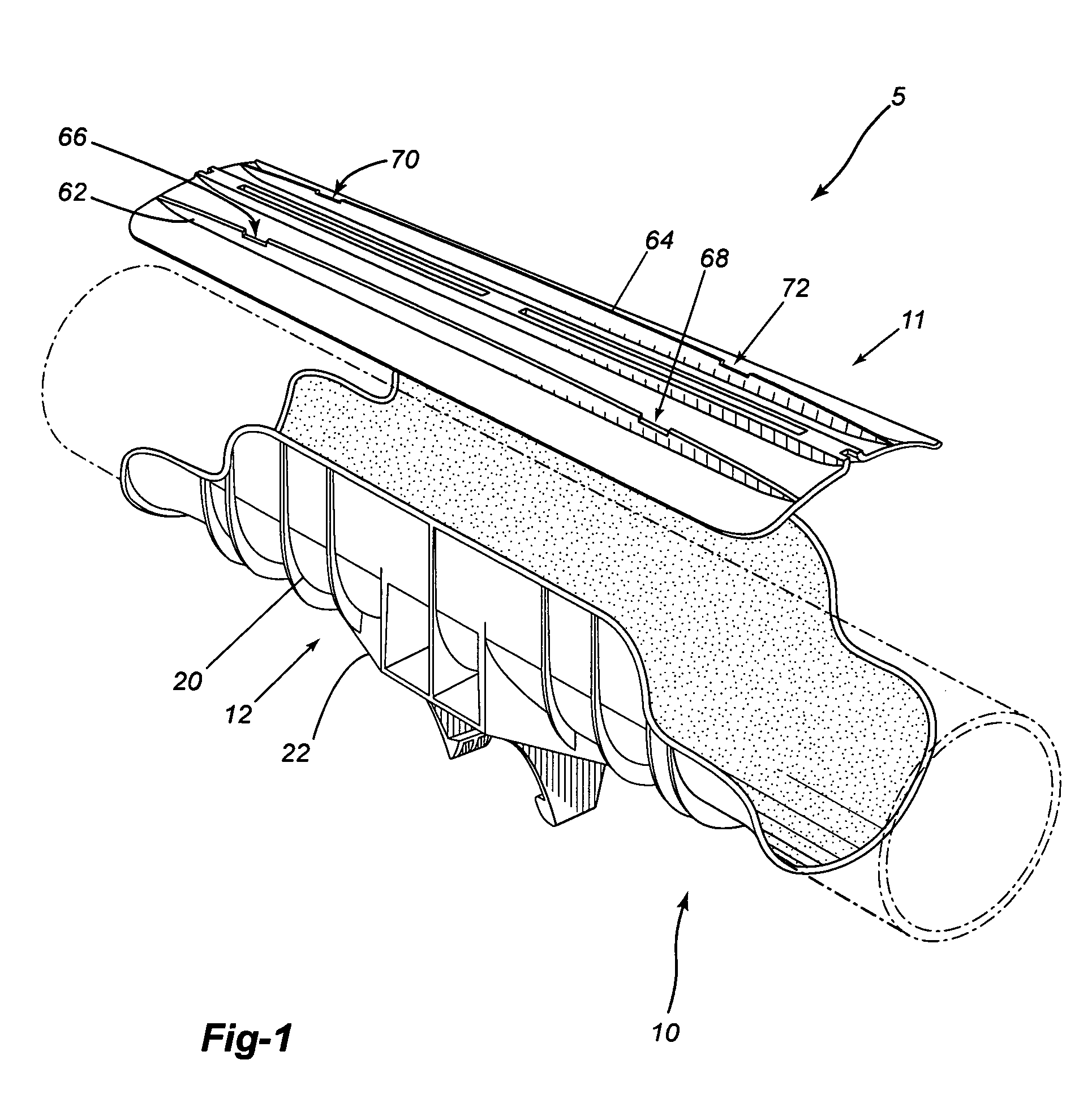
[0024]Referring to the drawings in greater detail, and by reference characters thereto, there is illustrated a pipe support assembly which is generally designated by reference numeral 5.

[0025]Pipe support assembly 5 is similar to that shown in application Ser. No. 10 / 966,568 carrying a filing date of Oct. 15, 2004, the disclosure of which is hereby incorporated by reference.

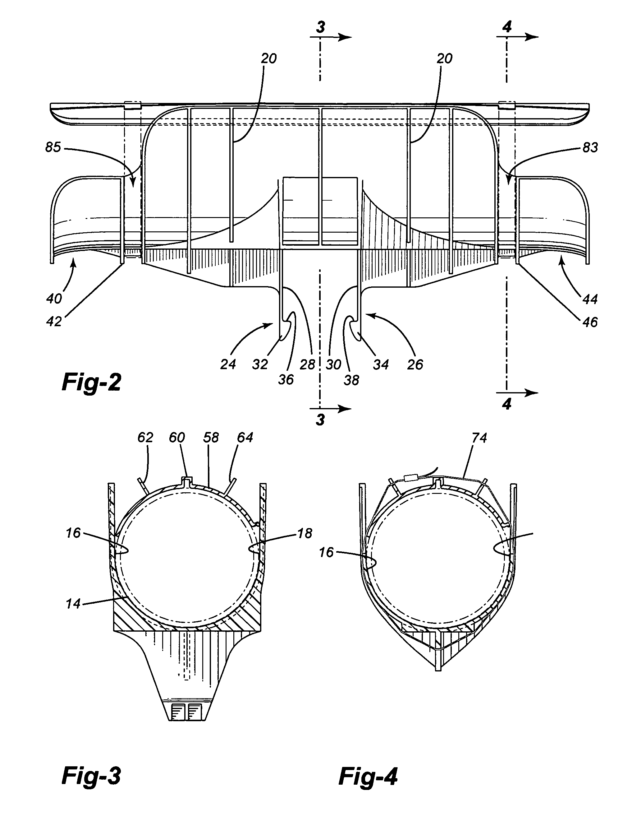
[0026]Pipe support assembly 5 includes a lower support member 10 and an upper support member 11. Lower support member 10 includes a central body portion generally designated by reference numeral 12 and which body portion 12 comprises a bottom wall 14 which of an arcuate configuration and upwardly extending side walls 16 and 18.

[0027]On the exterior facing surface of bottom wall 14 and side walls 16, 18 there are provided spaced transverse flanges 20. As will be noted, there are also provided longitudinally extending flanges 22, with three such flanges being illustrated.

[0028]Lower support 10 is designed to be att...


PUM


Abstract

A pipe support assembly which comprises a main body having a U-shaped recess therein, and a cover member for the body, the cover member having an arcuate configuration and being sized to fit between the first and second side walls, each of the cover members and body having a channel or a recess designed to receive a tie wrap to secure a pipe in position. The main body portion also has a clamping portion which comprises first and second resilient members.

Description

[0001]The present application is a continuation in part of application Ser. No. 11 / 282,373 filed Nov. 18, 2005 now abandoned.FIELD OF THE INVENTION[0002]The present invention relates to a pipe support system and more particularly, relates to a pipe support system for vertically extending pipes.BACKGROUND OF THE INVENTION[0003]In the installation of pipes and the like in various types of buildings and in particular pipes associated with air conditioning, refrigeration and heating, such as may be utilized in many commercial and industrial establishments, conventional practice is that the pipes are hung from the ceiling by strap hangers.[0004]The most common type of strap hanger employed in the industry comprises a metal strap having apertures for fastening purposes. The strap is looped about the pipe to be secured and then a fastening such as a screw or a similar member is secured to a substrate such as a beam or rafter through the apertures. A similar arrangement is employed when the...

Claims


Application Information

Patent Timeline
Patent Type & Authority Patents(United States)
IPC IPC(8): E21F17/02
CPCF16L3/02F16L3/24F16L3/1226F16L3/10F16L3/245
Inventor BOUDREAU, MARTINTHIBAULT, JEAN-PIERRE
Owner ARMACELL ENTERPRISE GMBH & CO KG
Why Eureka
Try Eureka