
Cab suspension linkage system

a suspension system and cab technology, applied in the direction of roofs, vehicle arrangements, transportation and packaging, etc., can solve the problems of affecting the ride quality and operator comfort of a work vehicle, the movement of the cab can be particularly severe, and the operator's comfort may also be adversely affected, so as to reduce acceleration, reduce acceleration, and improve ride quality

Inactive Publication Date: 2010-06-29
AGCO CORP
View PDF18 Cites 49 Cited by
  • Summary
  • Abstract
  • Description
  • Claims
  • Application Information

AI Technical Summary

Benefits of technology

[0011]Briefly described, a suspension system for reducing the accelerations transmitted from the vehicles tires or tracks through the frame, into the cab, and ultimately through to the operator is provided. By reducing the accelerations, the ride quality is greatly improved, allowing operators to operate a vehicle for longer periods of time without excessive fatigue.

Problems solved by technology

The ride quality and operator comfort of a work vehicle is adversely affected by vibrations or movement transmitted from the frame or chassis of the vehicle to the operator's cab.
Movement of the cab can be particularly severe in agricultural and construction equipment vehicles (e.g., tractors, combines, backhoes, cranes, dozers, trenchers, skid-steer loaders, etc.), because such vehicles typically operate on off-road surfaces or fields having a high level of bumpiness.
Operator comfort may also be adversely affected by the operation of various systems on a work vehicle.
The movement of the cab caused by surface bumps and the operation of vehicle systems cause both qualitative and quantitative problems.
An operator of such a vehicle experiences increased levels of discomfort and fatigue caused by the vibrations.
Productivity is decreased when an operator is forced to rest or shorten the work day, or is unable to efficiently control the work vehicle.
The operator is also less likely to be satisfied with a work vehicle that provides poor ride quality.
Under certain conditions, the frequency and magnitude of cab movement may force the operator to decrease driving speed, further decreasing productivity.
This, however, is not entirely satisfactory, and therefore the cab can be supported on rubber mounts that provide an improved degree of cushioning.

Method used


Image

  • Cab suspension linkage system
  • Cab suspension linkage system
  • Cab suspension linkage system

Examples


Embodiment Construction

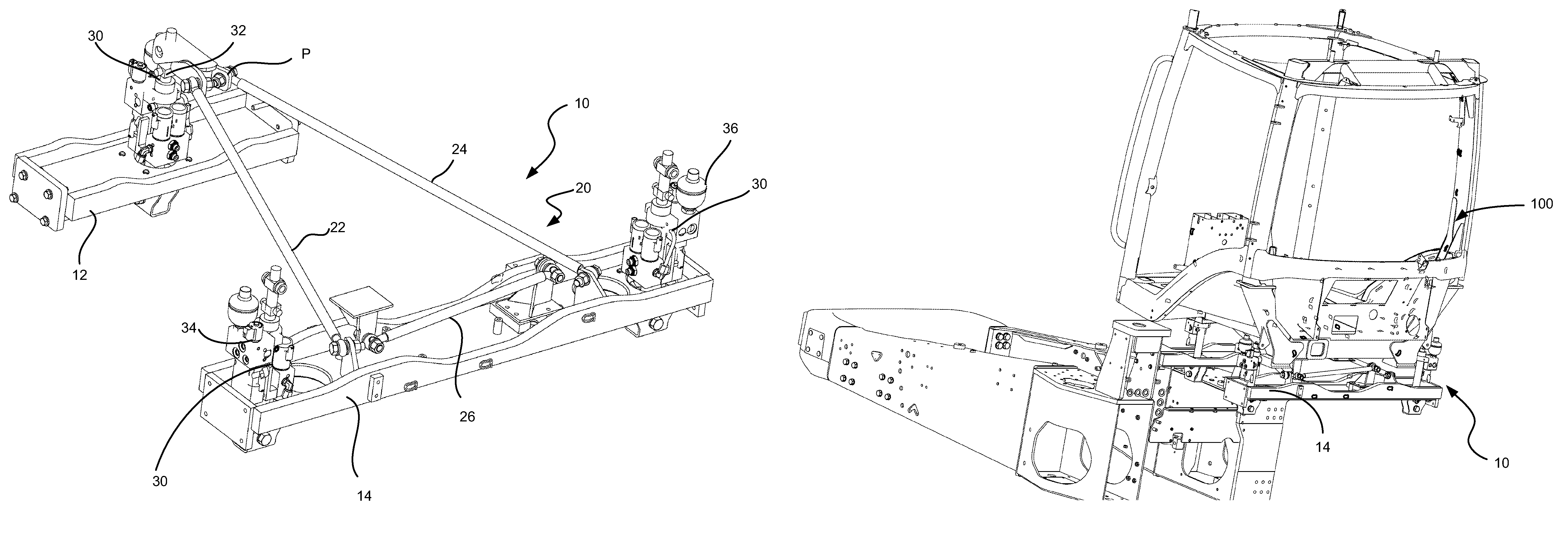
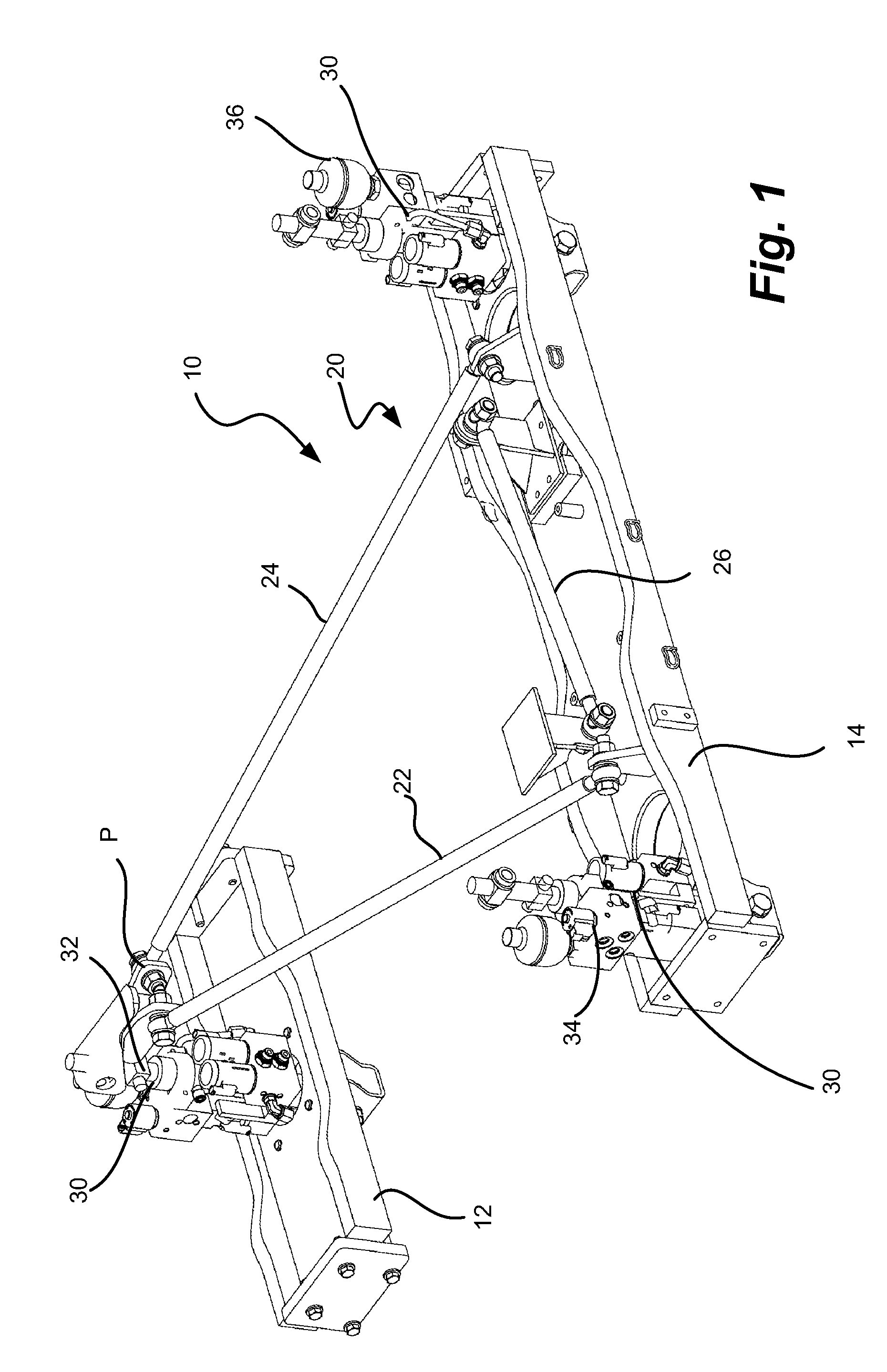
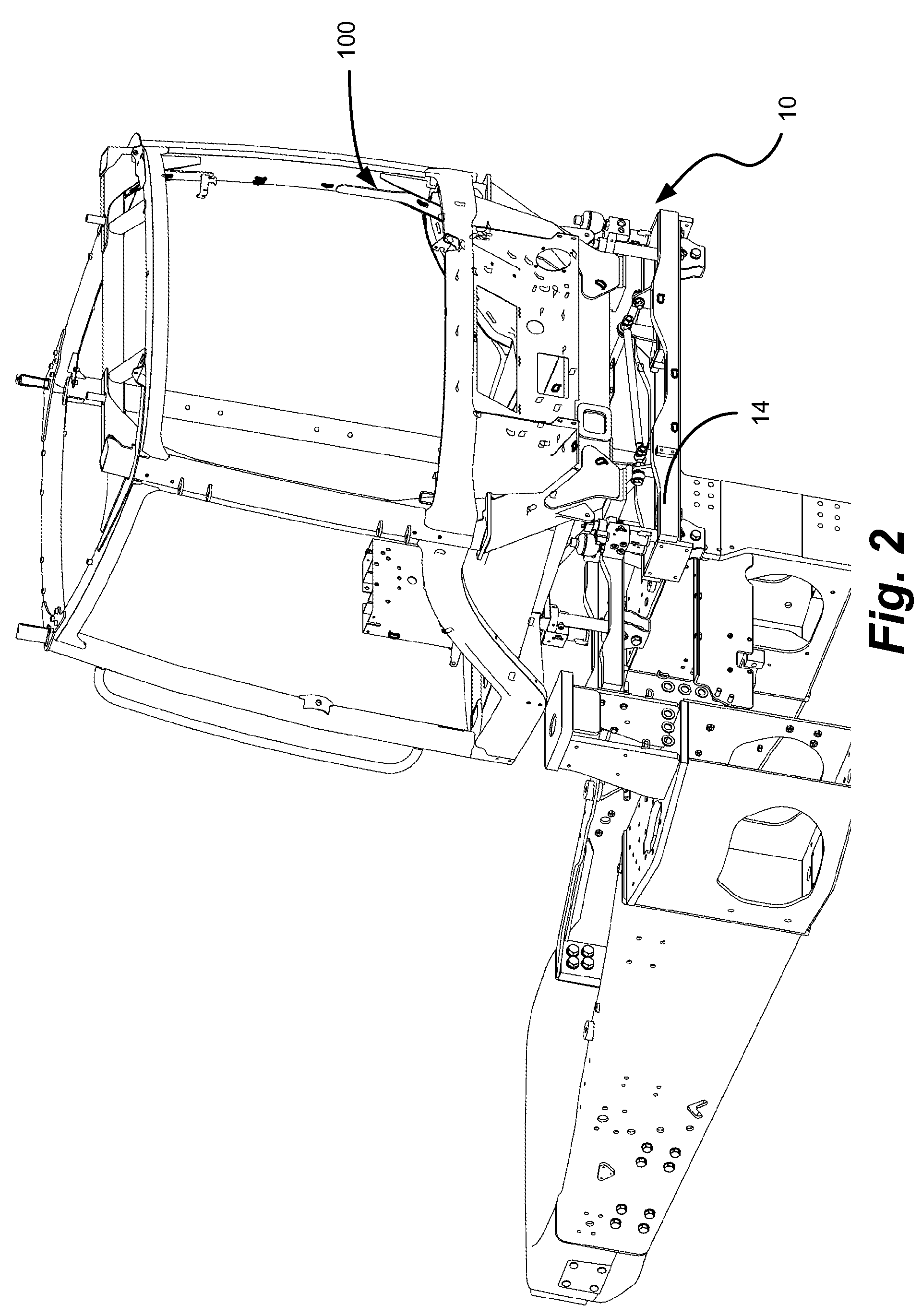
[0020]Referring now in detail to the figures, FIG. 1 illustrates a perspective view of a suspension system 10 for a cab 100 (FIGS. 2-4). The suspension system 10 comprises a linkage assembly 20, including a first fore-aft linkage 22, and second fore-aft linkage 24, and a lateral linkage 26.

[0021]The suspension system 10 communicates between the first chassis section 12 and the second chassis section 14 of the tractor, providing suspension control of damping members 30, one 32 located at the front of the first chassis section 12, and two 34, 36 located at the rear of the first chassis section 12 and in communication with the second chassis section 14.

[0022]The first chassis section 12 of the tractor thus is supported by the three damping members 30, preferably hydraulic cylinders, each acting independently. The linkage assembly 20 uses the set of three linkages 22, 24, 26 to restrain the cab. The two fore-aft linkages 22, 24 are attached at the rear to the second chassis section 14 o...


PUM


Abstract

An agricultural vehicle is described having a chassis and a cab mounted on the chassis. A suspension system for reducing the accelerations transmitted from the vehicles tires or tracks through the frame, into the cab, and ultimately through to the operator is provided. By reducing the accelerations, the ride quality is greatly improved, allowing operators to operate a vehicle for longer periods of time without excessive fatigue.

Description

BACKGROUND OF THE INVENTION[0001]1. Field of the Invention[0002]Various aspects of the present invention relate to a suspension system linkage arrangement for an agricultural vehicle having a cab resiliently supported on the chassis of the vehicle.[0003]2. Description of Related Art[0004]The ride quality and operator comfort of a work vehicle is adversely affected by vibrations or movement transmitted from the frame or chassis of the vehicle to the operator's cab. As the cab typically is built separately from, and later mounted on, the frame, and because the cab is separate from the frame, movement of the frame may be transmitted through and amplified by the connections between the cab and the frame.[0005]As the work vehicle travels across a surface, movement of the frame / chassis induces the operator's cab to pitch, roll and bounce. Movement of the cab can be particularly severe in agricultural and construction equipment vehicles (e.g., tractors, combines, backhoes, cranes, dozers, ...

Claims


Application Information

Patent Timeline
Patent Type & Authority Patents(United States)
IPC IPC(8): B62D33/06
CPCB62D33/0608
Inventor MURRAY, TIMSTEFFENSEN, CASEYWARD, WAYNE
Owner AGCO CORP
Learn More