Electrical cord locking connector

a technology of locking connectors and electrical cords, applied in the direction of coupling devices, coupling device connections, coupling parts engagement/disengagement, etc., can solve the problems of difficult to locate and reestablish the connection, lost time, and often remote live electrical outlets, so as to minimize interference in tight spaces

Inactive Publication Date: 2010-06-29
R C DESIGN & ENG
View PDF14 Cites 16 Cited by
  • Summary
  • Abstract
  • Description
  • Claims
  • Application Information

AI Technical Summary

Benefits of technology

[0006]In an embodiment of the present invention an electrical cord locking connector presents a streamlined profile and does not project radially outwardly at the junction of two interconnected cords, thereby minimizing interference in tight spaces through which the extension cords must be fed to service the job site. The connector joins the ends of the successive cords utilizing the outwardly projecting shoulder provided on the socket end of one cord, the socket cooperating with a latch member on the male end of a connecting cord to lock the two cords together at the mating ends without utilizing laterally projecting components that would prevent the normal feeding of the interconnected cables around corners and through openings and other restricted spaces.
[0007]In another aspect of the invention, a first electrical cord has an end provided with a plug having at least three prongs, one of which is connected to the grounding conductor of the cord, and a second cord has an end provided with a socket having at least three openings therein for receiving corresponding prongs of the first cord. The socket has an outwardly projecting shoulder for preventing improper mating of the prongs and openings, and the plug has a releasable latch member projecting therefrom which engages the shoulder when the plug and socket are properly mated to prevent separation of the plug and socket during use of the cords.
[0010]In yet another aspect of the present invention a replacement cord cap assembly is provided with a radially outwardly projecting shoulder at the face of the socket adjacent the two openings in the socket that receive corresponding current-carrying prongs of a male plug. The shoulder is received by a latch member on a connecting cord to prevent separation of the plug and socket.

Problems solved by technology

In the construction of buildings and other structures a live electrical outlet is often remote from the area where workmen require electric power to operate power tools of various types.
When power cords separate under stress, time is lost and the broken connection may be difficult to locate and reestablish.
Separation at the union of two cords or at the power cord of a tool is not uncommon, thereby causing a complete shut down of electrically-powered equipment.
Although locking devices have been proposed and used at the interconnection between two cords to assist in preventing separation, such devices may project radially and thus increase the transverse dimension of the cords at the connection, thereby presenting an obstacle to passing the connected cords through an opening or around a corner.
When this occurs, the cords cannot be advanced until fed by hand through or around the turn or other obstacle, also resulting in lost time.
This could be caused, for example, by an uncoupled end of an extension cord being exposed to moisture at a construction site.

Method used


Image

  • Electrical cord locking connector
  • Electrical cord locking connector
  • Electrical cord locking connector

Examples


Embodiment Construction

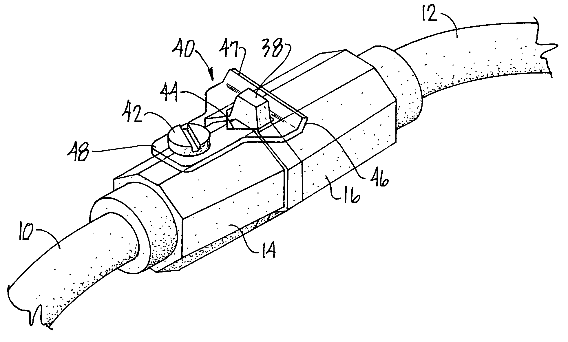
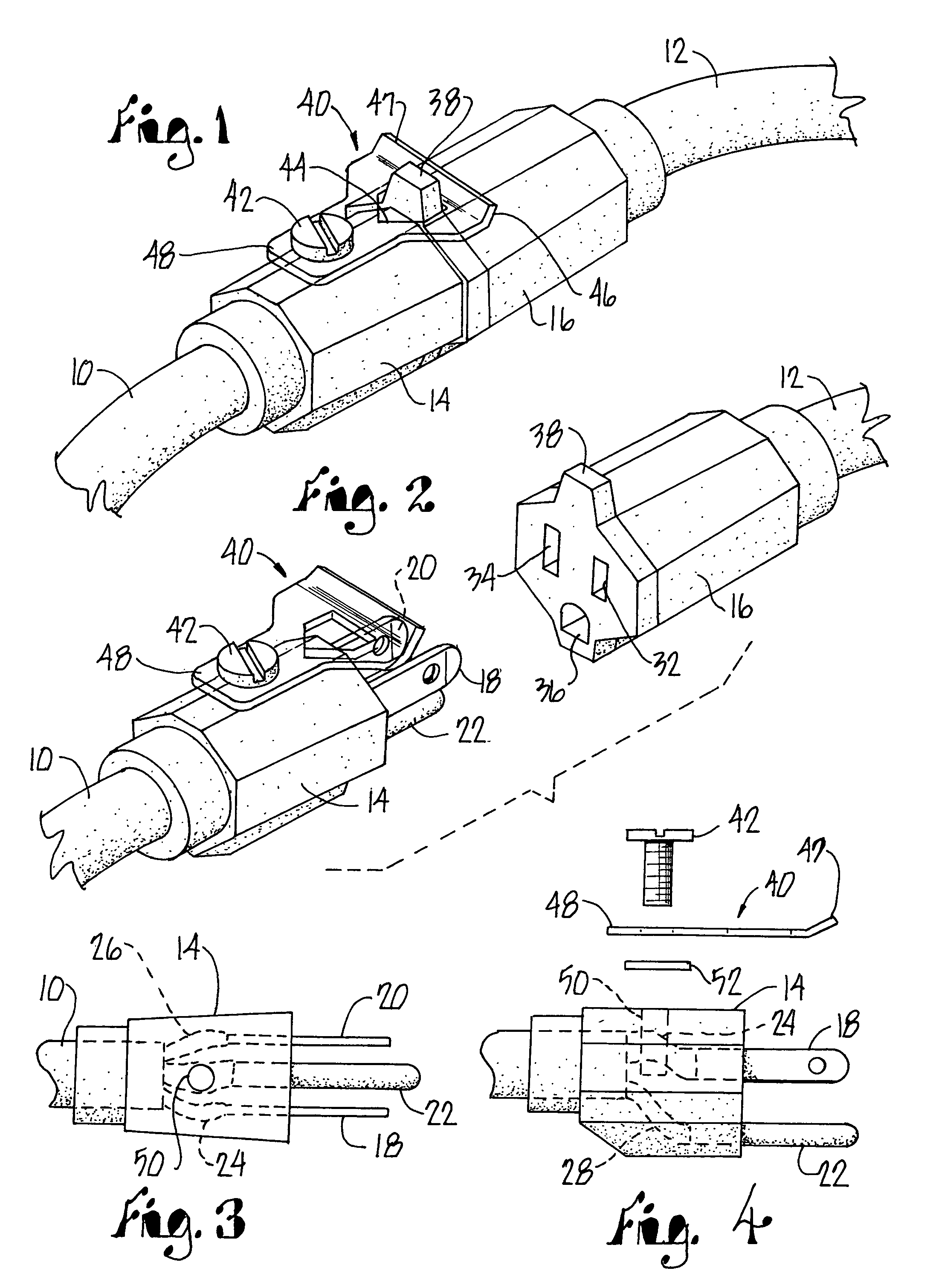
[0024]Referring initially to FIGS. 1 and 2, the mating ends of two extension cords 10 and 12 are shown connected together in FIG. 1 and separated in FIG. 2 in alignment with each other to show the male and female parts aligned prior to connecting cords 10 and 12 together. The end of cord 10 illustrated is provided with a male plug 14 which, in FIG. 2, is shown aligned with but withdrawn from a female socket 16 on the corresponding end of cord 12. It should be appreciated that cords 10 and 12 may extend 50 feet or more from the mating plug and socket illustrated in FIGS. 1 and 2 where the remote end of cord 10 would be provided with a socket, and the remote end of cord 12 would be provided with a plug. Accordingly, at a construction site where extension cords are used to connect power tools to a current source, series connected cords may extend hundreds of feet.

[0025]Referring also to FIGS. 3 and 4, plug 14 is typically provided with three prongs 18, 20 and 22. Extension cords for a ...


PUM


Abstract

An electrical cord locking connector joins electrical cords in series and presents a streamlined profile that minimizes interference in restricted spaces through which the cords must be fed to service a job site. The connector joins the ends of successive cords utilizing the outwardly projecting shoulder provided on the female socket of one cord in cooperation with a latch member on the male end of the connecting cord to lock the two cords together. A cord provided with a female end terminating in a replacement cord cap is provided with a socket presenting a generally circular face and an outwardly projecting shoulder at the face for engaging a releasable latch member of a mating plug, thereby preventing separation of the plug and socket under force until the latch member is disengaged.

Description

[0001]This application is a continuation-in-part of application Ser. No. 12 / 070,020, filed Feb. 14, 2008.FIELD OF THE INVENTION[0002]This invention relates to locking connectors for electrical extension and power cords to prevent separation of series-connected cords during use.BACKGROUND OF THE INVENTION[0003]In the construction of buildings and other structures a live electrical outlet is often remote from the area where workmen require electric power to operate power tools of various types. A typical example is a carpenter utilizing a power tool in a multi-floor structure or single floor areas having a long horizontal expanse. In these common construction environments electrical power tools are supplied with electricity using long extension cords connected in series, which may span long horizontal distances as well as vertically through several floors. When power cords separate under stress, time is lost and the broken connection may be difficult to locate and reestablish.[0004]Al...

Claims


Application Information

Patent Timeline
Patent Type & Authority Patents(United States)
IPC IPC(8): H01R13/62
CPCH01R13/6275H01R13/6392H01R24/22H01R24/30H01R13/652H01R2103/00
Inventor CARMITCHEL, RICHARD A.
Owner R C DESIGN & ENG
Why Eureka
Try Eureka