Premolded housing

a pre-molded and housing technology, applied in the direction of coupling device details, coupling device connection, basic electric elements, etc., can solve the problems of unsuitability of molded housings, and achieve the effects of cost-effective and rapid manufacturing of pre-molded housings, great stability, and great variability in installation

Inactive Publication Date: 2005-06-23
ROBERT BOSCH GMBH
View PDF3 Cites 11 Cited by
  • Summary
  • Abstract
  • Description
  • Claims
  • Application Information

AI Technical Summary

Benefits of technology

[0008] The design of the premolded housing according to the present invention, having a housing body and laterally extending side support areas that may be bent over in direction-changing areas, allows great stability and great variability in the installation when mounted vertically, depending on the installation space and the need for accessibility of the soldering points. The side support areas may optionally be bent in one of two directions, and furthermore, soldering tabs of the side support areas and of the connector pins may optionally also be bent in one of two directions.
[0009] Cost-effective and rapid manufacturing of the premolded housing is possible by molding the housing on a supporting strip or leadframe strip, followed by cutting or stamping out the leadframe, preferably with one cut, and bending over the side support areas.

Problems solved by technology

Because of their mechanical, optical or thermal properties, generally the detector chips may not be completely coated with plastic or a molding compound, so that the use of molded housings is unsuitable; however, in the case of premolded housings the radiation may enter through the open front of the premolded housing.

Method used


Image

  • Premolded housing
  • Premolded housing
  • Premolded housing

Examples


Embodiment Construction

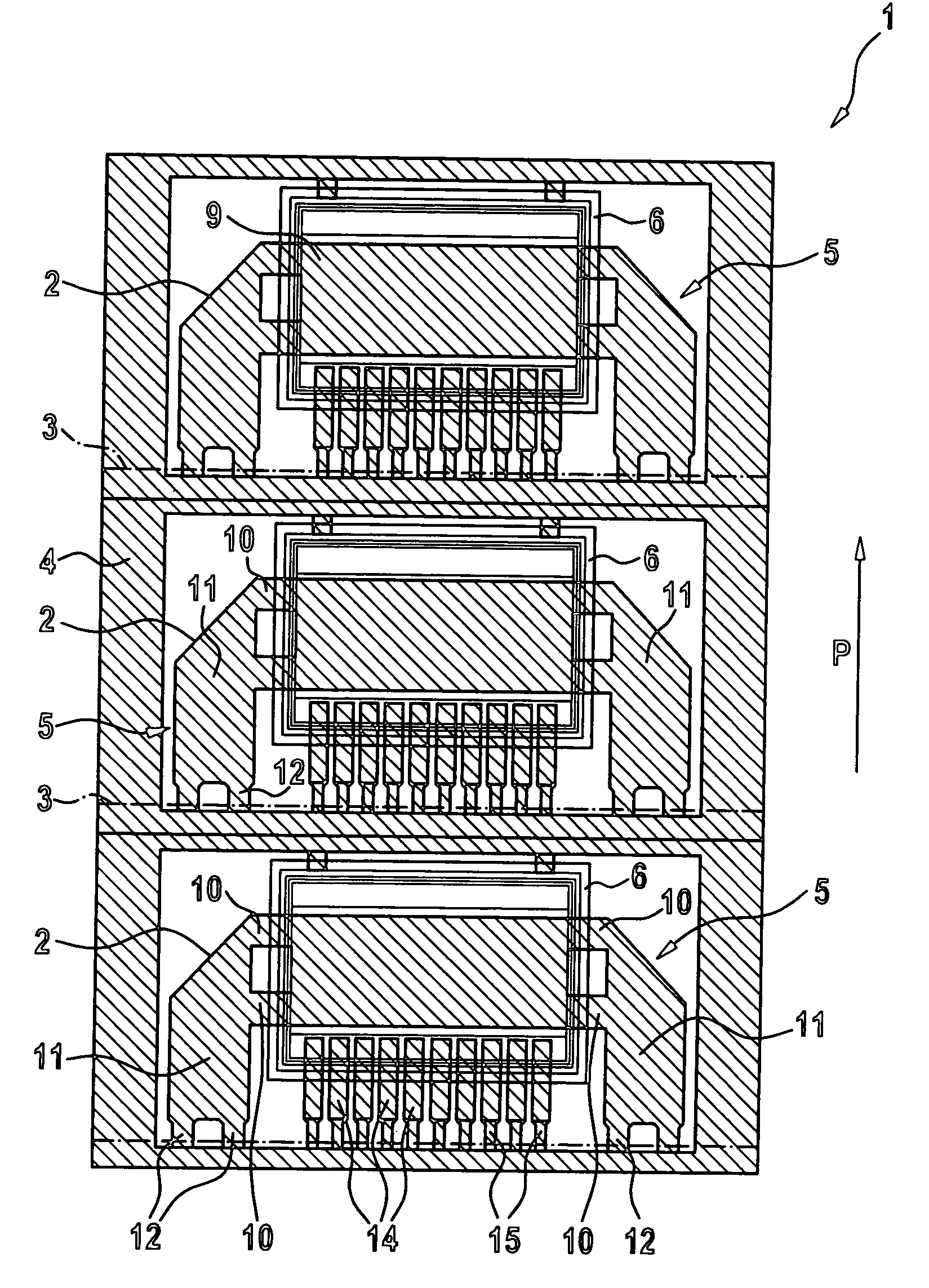
[0020] A leadframe strip 1 is manufactured, for example as a stamped part, from a metal, for example copper, and has a continuous ladder-shaped frame 4 with webs 4a, and a plurality of leadframe structures 5, prestamped in frame 4 and arranged in sequence in a direction of symmetry P, for leadframes 2 to be separated out later.

[0021] According to an example embodiment of the present invention, housing bodies 6 may be manufactured directly by extrusion coating leadframe structures 5 in unseparated leadframe strip 1 with a plastic material or a molding compound based on synthetic resin. In FIG. 1 the positions of premolded housing 6 are already drawn in with lines on the individual leadframe structures 5.

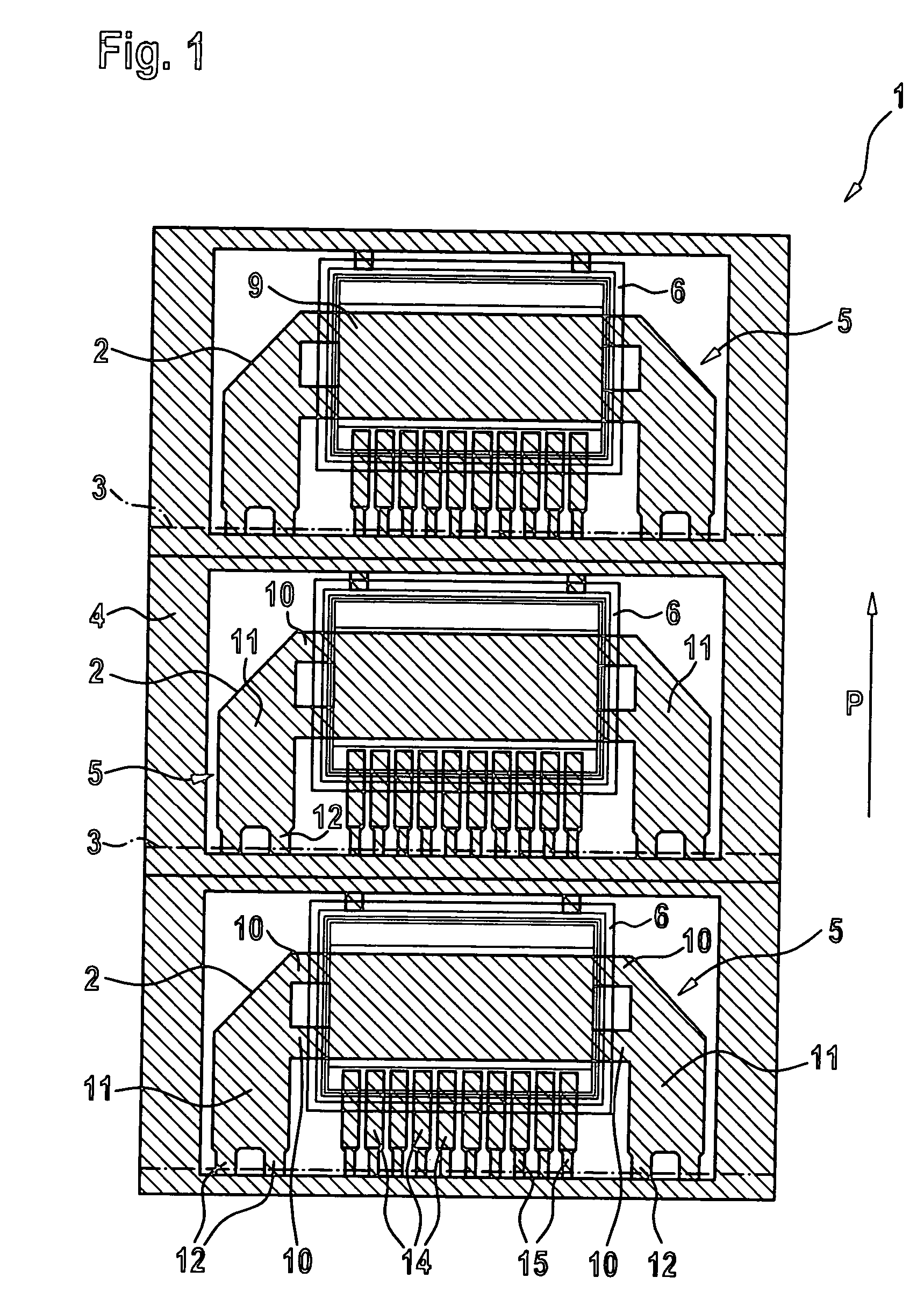
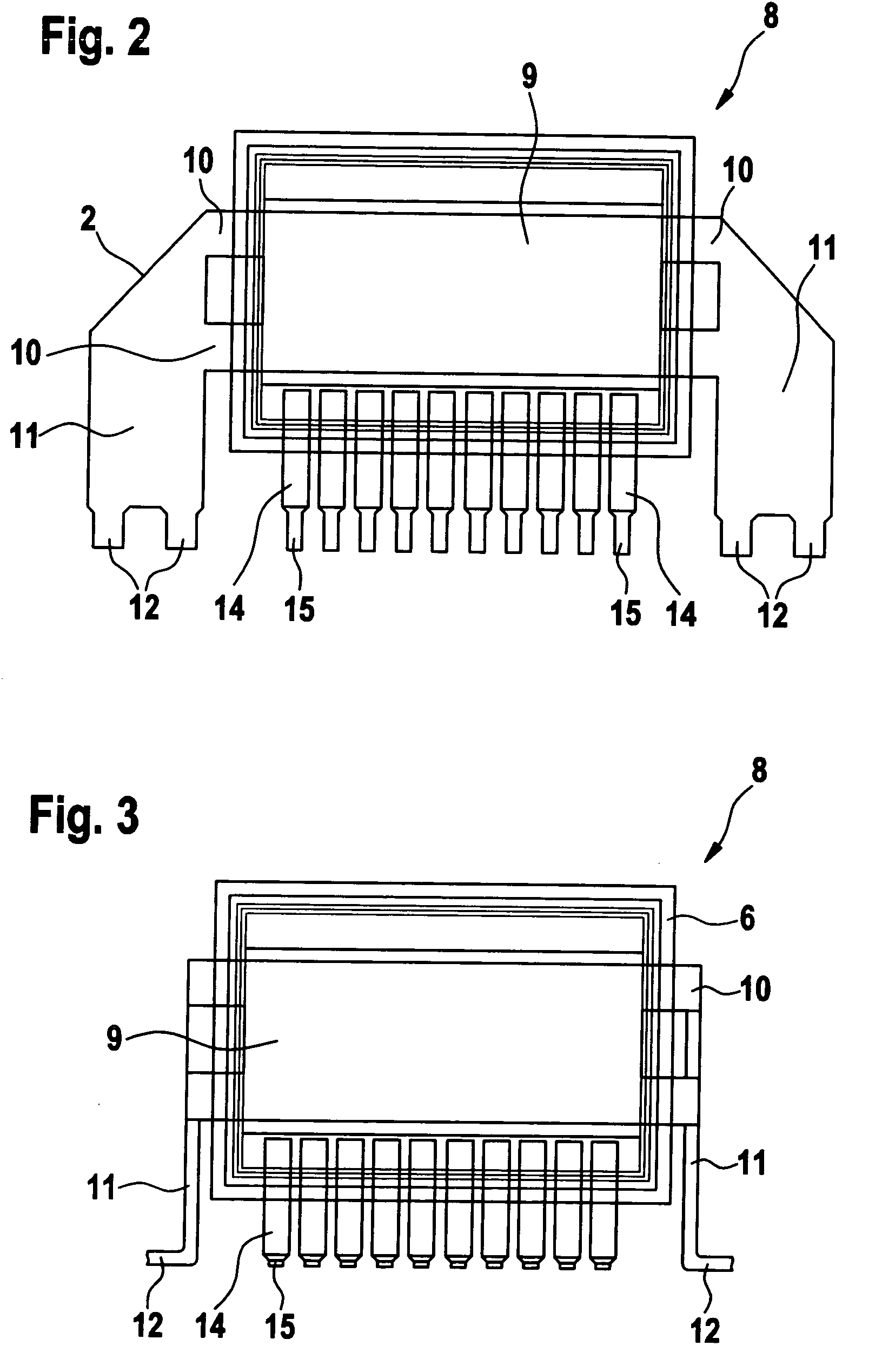
[0022] Each leadframe 2 has in its middle area a die pad 9, which is connected in both lateral directions, i.e., orthogonally to the direction of symmetry P—through a direction-changing area 10 to a left and right side support area 11. Side support areas 11 each extend downward, i.e...


PUM


Abstract

A premolded housing for receiving a component. The housing includes a housing body made of a plastic material or molding compound material, a leadframe of metal, partially molded into the housing body, having a plurality of connector pins projecting from a connecting side of the housing body, for contacting a substrate, a die pad for receiving the component, and two side support areas connected to the die pad via direction-changing areas, the direction-changing areas projecting from housing body on opposite sides and side support areas being situated outside of the housing body, and side support areas and the connector pins extending in the same connecting direction for installation on the substrate. After the soldering tabs and the side support areas have been bent over, the premolded housing is mounted vertically on a substrate, for example a circuit board, and in particular receives a thermopile chip for a gas sensor.

Description

FIELD OF THE INVENTION [0001] The present invention relates to a premolded housing for receiving a detector chip, a component made up of such a premolded housing and a chip received therein, as well as a device having a substrate and such a component. BACKGROUND INFORMATION [0002] Premolded housings have a housing body which may be made of a plastic material or a molding compound based on epoxy resin, and a generally multiple-piece supporting strip of metal, generally called the leadframe. The premolded housing is produced in a molding process by extrusion-coating the leadframe with the plastic material or molding compound. Connector pins or housing tabs for contacting on a circuit board protrude, generally parallel to the housing floor or a possible die pad, generally on two sides or on all four sides of the premolded housing. A detector chip may subsequently be set into the premolded housing—onto the housing floor or preferably onto a middle area of the leadframe used as a die pad...

Claims


Application Information

Patent Timeline
Patent Type & Authority Applications(United States)
IPC IPC(8): H01L23/08G01D11/24H01L21/52H01L23/28H01L23/50H01R9/03H01R13/66H01R43/24
CPCH01R43/24H01R13/6683
Inventor LUDWIG, RONNY
Owner ROBERT BOSCH GMBH
Why Eureka
Try Eureka