Instrument container having multiple chambers with flow pathways therebetween

a technology of flow pathways and instruments, applied in the field of instruments and instruments with multiple chambers, can solve the problems of difficult to put liquid microbial deactivation fluid in contact with the external surfaces of lumened instruments engaged with the connectors, and the connectors must be identified

Active Publication Date: 2010-06-29
AMERICAN STERILIZER CO
View PDF21 Cites 9 Cited by
  • Summary
  • Abstract
  • Description
  • Claims
  • Application Information

AI Technical Summary

Benefits of technology

[0009]An advantage of the present invention is the provision of a multi-chamber instrument container, wherein a pressure differential is maintained between the chambers to induce liquid microbial deactivation fluid to flow through internal pathways of an instrument located therein.
[0010]Another advantage of the present invention is the provision of a multi-chamber instrument container for microbially deactivating instruments placed therein, the container eliminating the need to connect ports of the instruments to connectors of a liquid deactivation fluid conduit,
[0011]Still another advantage of the present invention is a multi-chamber instrument container that can be configured to simultaneously process instruments of varying dimensions.
[0012]Yet another advantage of the present invention is a multi-chamber instrument container that includes a flowable seal between the chambers.
[0013]These and other advantages will become apparent from the following description of a preferred embodiment taken together with the accompanying drawings and the appended claims.

Problems solved by technology

One drawback to this approach is that the proper connectors must be identified and selected for connection with the ports of the lumened instrument.
Another drawback to this approach is that it can be difficult to put liquid microbial deactivation fluid in contact with the external surfaces of the lumened instrument that are engaged with the connectors.

Method used


Image

  • Instrument container having multiple chambers with flow pathways therebetween
  • Instrument container having multiple chambers with flow pathways therebetween
  • Instrument container having multiple chambers with flow pathways therebetween

Examples


Embodiment Construction

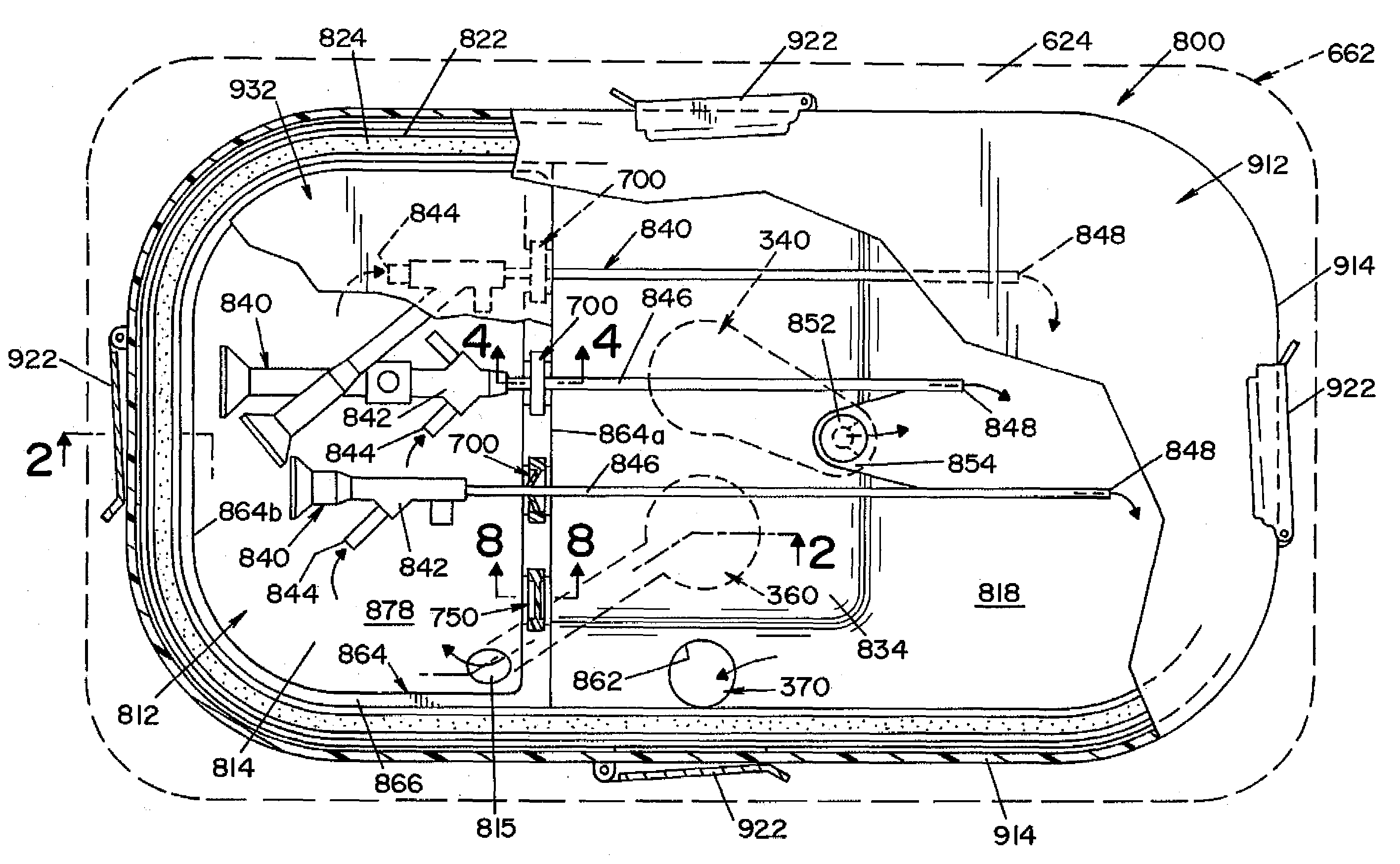
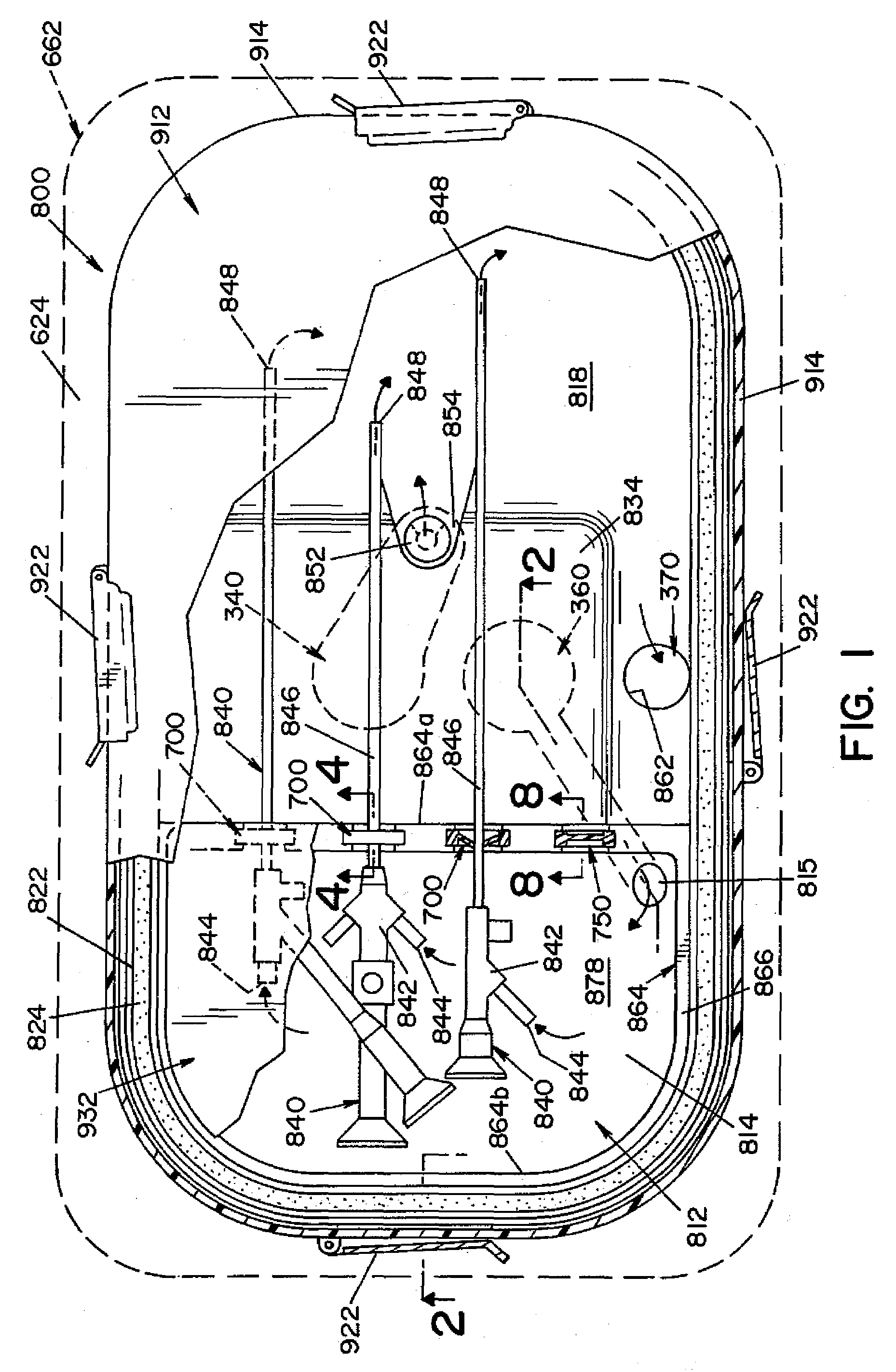
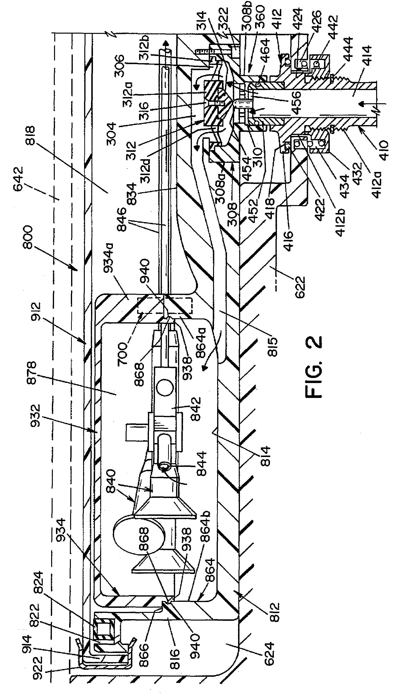
[0023]Referring now to the drawings wherein the showings are for the purpose of illustrating an embodiment of the invention only, and not for the purpose of limiting same, FIGS. 1 and 2 show an instrument container 800 according to an embodiment of the present invention. Instrument container 800 is generally comprised of tray 812 and lid 912 that is attachable to tray 812. Tray 812 is generally cup-shaped and has a bottom wall 814 and a continuous side wall 816 that extends about the periphery of bottom wall 814 to one side thereof. Bottom wall 814 and side wall 816 define a cavity or chamber 818 dimensioned to receive instruments 840 therein.

[0024]The upper edge of side wall 816 is shaped to define a channel 822, best seen in FIG. 2. Channel 822 extends continuously about the upper edge of side wall 816. Channel 822 is dimensioned to receive a continuous, flexible seal 824. In the embodiment shown, seal 824 is an inflatable seal. An air conduit (not shown) communicates with seal 82...


PUM

PropertyMeasurementUnit
sizeaaaaaaaaaa
diameteraaaaaaaaaa
outer diameteraaaaaaaaaa

Abstract

A multi-chamber instrument container for microbially deactivating medical, dental, veterinary and mortuary instruments and articles. A pressure differential between chambers causes fluid flow therebetween, thus flowing fluid through internal passages of instrument extending between the chambers.

Description

FIELD OF THE INVENTION[0001]The present invention relates generally to disinfection or deactivation of medical, dental, pharmaceutical, veterinary or mortuary instruments and devices, and more particularly, to an instrument container having multiple chambers with flow pathways therebetween.BACKGROUND OF THE INVENTION[0002]Medical, dental, pharmaceutical, veterinary or mortuary instruments and devices, are routinely exposed to blood or other body fluids during medical procedures. Following such procedures, a thorough cleaning and anti-microbial deactivation of the instruments is required before subsequent use. Liquid microbial deactivation systems are now widely used to clean and deactivate instruments that cannot withstand the high temperature of a steam deactivation system. Liquid microbial deactivation systems typically operate by exposing the instruments to a liquid deactivation fluid, such as peracetic acid or some other strong oxidant. In such systems, the instruments to be cle...

Claims


Application Information

Patent Timeline
Patent Type & Authority Patents(United States)
IPC IPC(8): A61L2/00
CPCA61B1/123A61B19/0256A61B19/026A61L2/26A61L2/22A61L2202/24A61L2202/121A61L2202/122A61B50/20A61B50/30
Inventor HORACEK, JEFFREY R.JETHROW, CHRISTOPHER A.
Owner AMERICAN STERILIZER CO
Why Eureka
Try Eureka