Fluid logic tool for a subterranean well

a technology for logic tools and subterranean wells, which is applied in the direction of fluid removal, borehole/well accessories, construction, etc., can solve the problems of ball seats obstructing access to tools, control lines are always subject to some type of failure, and process can be very expensiv

Inactive Publication Date: 2010-04-15
OILTOOL ENG SERVICES
View PDF11 Cites 106 Cited by
  • Summary
  • Abstract
  • Description
  • Claims
  • Application Information

AI Technical Summary

Benefits of technology

[0048]The inner tool may use any type of seal that engages pressure wise, with the I.D. of the outer tool. For example, each set of seals that are adjacent to the fluid flow ports may be Labyrinth type seals, elastomer seals, non-elastomeric seals, or any type of seal that directs fluid flow into the ports. The seal can be as simple as two metal surfaces, the O.D. of the inner tool and the I.D. of the outer tool, i.e., the clearance between the two surfaces is sufficient to direct fluid into the outer tool. The seal does not have to be a prefect seal to actuate the outer tool, but must seal sufficiently to cause a reliable pressure differential across the “balanced piston” in the outer tool to actuate the outer tool. The Labyrinth seal, a series of metal grooves, is the preferred seal due to its clearance with the I.D. of the outer tool, its ability to restrict flow past it, and its robustness.

Problems solved by technology

A ball or ball seat can obstruct access the tools below the packer.
Packers are also set on wireline or electric line where a Baker E-4 generates sufficient pressure and force to set a packer, but this method is usually limited to setting sump packers or setting a single completion packer with minimal weight hanging on the bottom of the packer.
This process can be very expensive and control lines are always subject to some type failure.
The problem with shifting keys is that the shifting tools tend to jump out of the mating profiles for various reasons and shifting force is limited as a result.
Sliding sleeves that have been downhole for extended periods of time tend to collect scale and can become difficult to shift.
Also, it may be possible to reach sliding sleeves in a deviated well with coiled tubing and a shifting tool, but when the shifting tool engages the sliding sleeve; the drag forces on the coiled tubing through the bend limit the ability to shift the sliding sleeves.
Also, the number of shifting tool key profiles and mating sliding sleeve profiles is limited, so shifting selectivity in multiple zones is also limited.
Furthermore, shifting tool collets or keys sometimes break leaving unwanted debris in the hole.
In many cases annulus pressure is not possible due to the completion configuration.
“J’ mechanisms sometimes jam up and don't work or the operator gets confused and doesn't know where he is at in the “J”.
A problem exists when it is desired to fire multiple guns at different times in multiple zones, especially with single trip TCP (tubing conveyed perforating) guns.
Methods are lacking to selectively fire these guns in multiple zones without coming out of the hole.

Method used


Image

  • Fluid logic tool for a subterranean well
  • Fluid logic tool for a subterranean well
  • Fluid logic tool for a subterranean well

Examples


Embodiment Construction

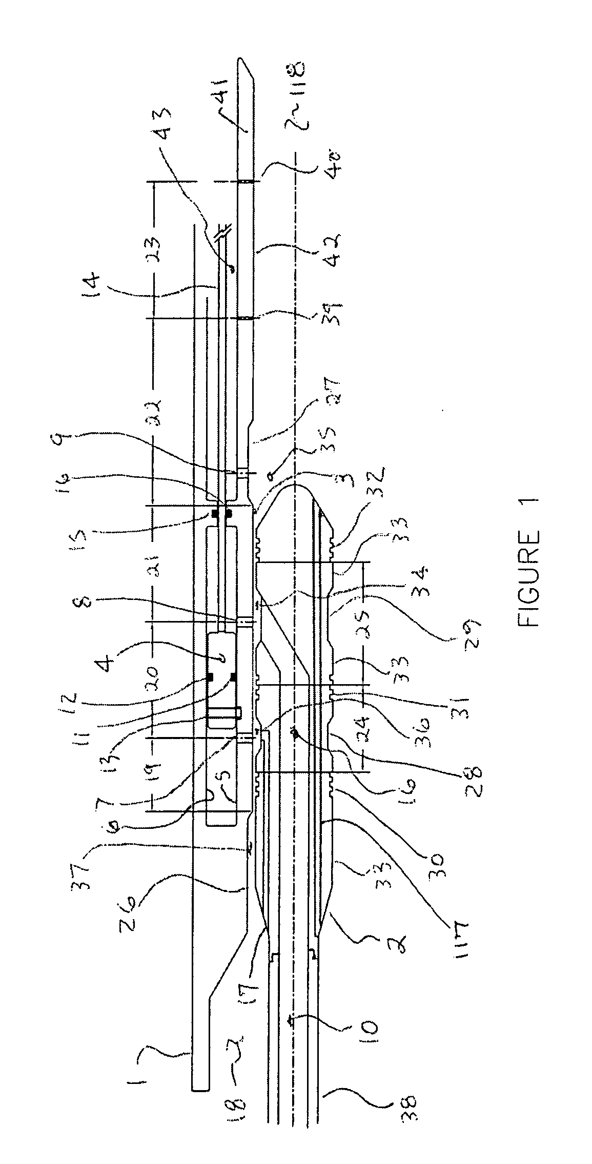
[0059]FIG. 1 consists of a “Completion Fluid Logic Tool” (CLT, also referred to as the outer tool) 1 with a “Service Fluid Logic Tool” (SLT, also referred to as the inner tool) 2 positioned in the inside bore 3 of the CLT 1. The SLT 2 and CLT 1 may take on several forms as described later in the description. A Piston 4 is located between an inner housing 5 and outer housing 6 with ports 7 and 8 and 9 adjacent to the piston 4. Based on the type or form of the CLT, different porting arrangements may be used.

[0060]The objective of the porting arrangements, for example port 7 and port 8, is to allow tubing (internal) pressure 10 to act on each side of the piston 4, on both sides of seals 11 and 12, in order to keep the piston 4 in a pressure balanced, or near pressure balanced, condition so that any increase in tubing pressure 10, for any reason, does not cause the piston 4 to move. If the piston 4 does not move, the CLT 1 remains in a dormant state and does not function. The piston 4 m...


PUM


Abstract

An operating tool uses programmed fluid logic provided by use of flow paths including pre-determined spaced ports and varying orifice sizes to provide discreet pressures and fluid flow rates upon pressure differential sensitive devices, such as a membrane or piston, in operative communication with an operative sleeve to manipulate one or more secondary tools, and/or to perform a service, such as, for example, acidzing or stimulation or injecting proppants within the well. The tool remains “immune” to internal well hydraulic or hydrostatic pressures, if desired, until the fluid logic is achieved. The fluid logic is adjustable for activation of tools sequentially by making changes in the port spacing and fluid relief profiles so that all tools can be actuated by a single geometry of fluid flow paths, or each tool can have its own unique fluid flow geometry so it becomes hydraulically coded.

Description

CROSS-REFERENCE TO RELATED APPLICATIONS[0001]This application is a utility application based upon: (1) Provisional application Ser. No. 61196326, filed Oct. 15, 2008, entitled “Fluid Logic Tool for a Subterranean Well”, Gregg W. Stout, inventor; and (2) Provisional application Ser. No. 61207131, filed Feb. 9, 2009, entitled “Fluid Logic Tool”, Gregg W. Stout, inventor.BACKGROUND OF THE INVENTION[0002]1. Field of the Invention[0003]This invention relates to downhole tools for oil and gas wells and similar applications and more particularly to servicing or completing wells.[0004]2. Brief Description of Prior Art[0005]Many types of downhole tools are conveyed into the well for various types of applications in order to produce oil and gas from underground formations. As an example, typical downhole tools are packers, sliding sleeves, ball valves, flapper valves, and perforating guns, and gravel pack screens, to mention a few. Well formations may have one or more producing zones where ea...

Claims


Application Information

Patent Timeline
Patent Type & Authority Applications(United States)
IPC IPC(8): E21B34/00
CPCE21B23/04E21B23/06E21B2034/007E21B41/00E21B34/10E21B2200/06E21B23/0412E21B23/042
Inventor STOUT, GREGG W.
Owner OILTOOL ENG SERVICES
Why Eureka
Try Eureka