Acoustic waveguide plate with nonsolid cores

a waveguide plate and non-solid core technology, applied in the field of acoustic waveguide plates with non-solid cores, can solve the problems of reducing the clarity of the information provided by the ultrasonic system, reducing and large lens size, so as to reduce the attenuation of the ultrasonic signal, reduce the size of the lens, and reduce the strength of the puls

Active Publication Date: 2010-06-29
QUALCOMM INC
View PDF14 Cites 2 Cited by
  • Summary
  • Abstract
  • Description
  • Claims
  • Application Information

AI Technical Summary

Benefits of technology

[0013]The waveguide core may be a liquid such as water, alcohol or mineral oil. Since liquids have a shear wave propagation velocity that is or approaches zero, liquids do not propagate shear stresses to the same extent as solids. A resulting advantage of a waveguide having a liquid core may be that there is no low-frequency cut-off or a very low low-frequency cut-off, thereby alleviating a limitation of prior art waveguides.
[0014]Alternatively, the waveguide core may be a colloidal gel, such as vinyl plastisol, gelatin dissolved in water, or silicone gel. Although a colloidal gel may have a shear wave propagation velocity that is greater than liquids, its shear wave propagation velocity is less than solids that may be used for the core of a waveguide. An advantage to using a colloidal gel core is that the colloidal gel may be easier to handle than a liquid when fabricating a waveguide since a colloidal gel will not easily leave a tubular cladding. Another advantage of using a colloidal gel for the core is that colloidal gels may have less attenuation of an ultrasonic signal than a core which is a solid material, but a colloidal gel core will have more attenuation than the base liquid that comprises such a gel.

Problems solved by technology

The result is that by the time the ultrasonic energy arrives at the receiver, the strength of the pulse has greatly diminished.
Such scattering tends to reduce the clarity of the information provided by an ultrasonic system.
The primary drawbacks in this methodology have been (a) large lens size, and (b) the inability to create short transmission paths for transferring the ultrasonic energy.
Additionally, compound lens assemblies must frequently be fabricated to tight mechanical tolerances, which results in increased costs.

Method used


Image

  • Acoustic waveguide plate with nonsolid cores
  • Acoustic waveguide plate with nonsolid cores
  • Acoustic waveguide plate with nonsolid cores

Examples


Embodiment Construction

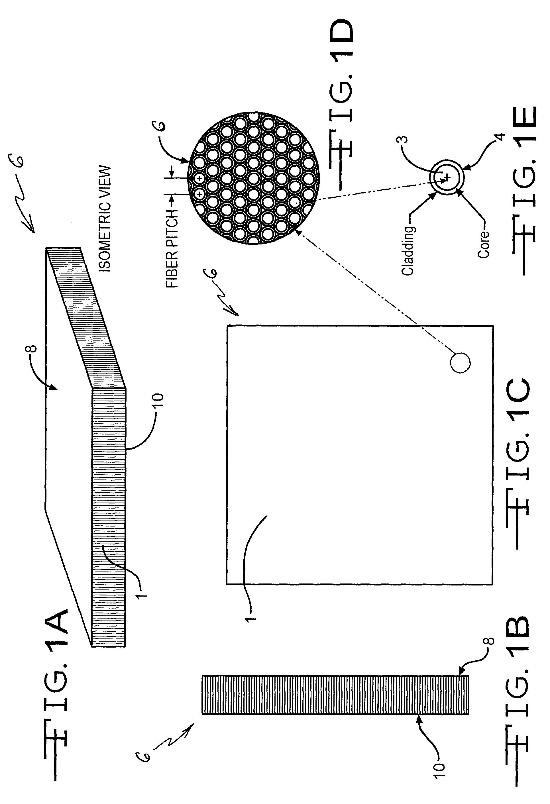
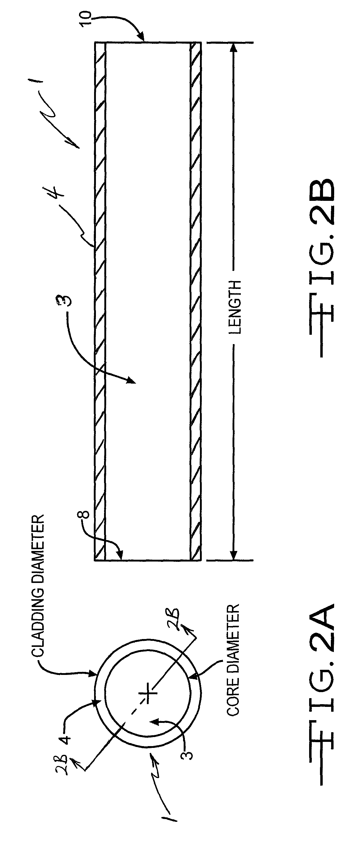
[0032]FIGS. 1A through 1E depict an embodiment of the invention in which a plurality of substantially parallel ultrasonic waveguides 1 are held together into a single assembly. The assembly is shown in FIGS. 1A, 1B and 1C as a plate 6 of waveguides 1. The ultrasonic waveguides 1 may be fibers, and may be thought of as conduits that transmit acoustic wave energy, such as ultrasonic energy, from a first end-surface 8 of the waveguide 1 to a second end-surface 10 of the waveguide 1. Each waveguide 1 in the plate 6 may be used to convey a different ultrasonic signal from one side of the plate 6 to the other side. In order to preserve the information being transmitted by the waveguides, the relative positions of the first end-surfaces 8 of the waveguides 1 may be positioned substantially the same as the relative positions of the second end-surfaces 10 of the waveguides 1.

[0033]In an embodiment of the invention, an assembly of waveguides 1 is formed so that ultrasonic energy may be conduc...


PUM

PropertyMeasurementUnit
thickaaaaaaaaaa
shear-wave propagation velocityaaaaaaaaaa
lengthaaaaaaaaaa

Abstract

An acoustic (sound or ultrasound) wave transmitter having a plurality of waveguides is described, and a method of making such a transmitter is described. Each waveguide may have a cladded core. The core may be a liquid such as water, alcohol or mineral oil. Alternatively, the core may be a colloidal gel, such as gelatin dissolved in at least one of water, vinyl plastisol or silicone gel. The cladded core is capable of transmitting acoustic wave energy from a first end surface to a second end surface of the cladded core. The waveguides may be substantially fixed relative to each other by a binder. The binder may be formed by fusing the claddings together, potting a material between the waveguides and / or mechanically holding the waveguides.

Description

CROSS-REFERENCE TO RELATED APPLICATION[0001]This application is a continuation-in-part of U.S. patent application Ser. No. 11 / 761,101, which was filed on Jun. 11, 2007, and this application claims the benefit of priority to U.S. patent application Ser. No. 11 / 761,101. U.S. patent application Ser. No. 11 / 761,101 claims the benefit of priority to U.S. provisional patent application Ser. No. 60 / 804,412, which was filed on Jun. 9, 2006. This continuation-in-part patent application also claims the benefit of U.S. patent application 60 / 804,412.FIELD OF THE INVENTION[0002]The present invention relates to devices for transmitting information using longitudinal waves, such as sound and ultrasound. The term “acoustic” is used to refer collectively to sound waves and ultrasound waves.BACKGROUND OF THE INVENTION[0003]It is well known to use acoustic waves, such as ultrasonic energy, to determine information about an object. For example, in non-destructive testing, ultrasonic energy pulses are u...

Claims


Application Information

Patent Timeline
Patent Type & Authority Patents(United States)
IPC IPC(8): C08K5/15G01S1/72
CPCG10K11/24B06B3/00G10K11/18
Inventor SCHNEIDER, JOHN K.KITCHENS, JACK C.
Owner QUALCOMM INC
Why Eureka
Try Eureka