
Three-dimensional image display apparatus and method

a three-dimensional image and display apparatus technology, applied in image analysis, image enhancement, instruments, etc., can solve the problems of difficult to determine which part of a measuring object is measured, difficult to correlate 3d data obtained with the three-dimensional position measurement apparatus and site conditions, and not everyone can always make recognition easy, etc., to achieve easy recognition, easy recognition, and easy determination of positional correspondence in the stereo image

Active Publication Date: 2010-06-29
KK TOPCON
View PDF20 Cites 6 Cited by
  • Summary
  • Abstract
  • Description
  • Claims
  • Application Information

AI Technical Summary

Benefits of technology

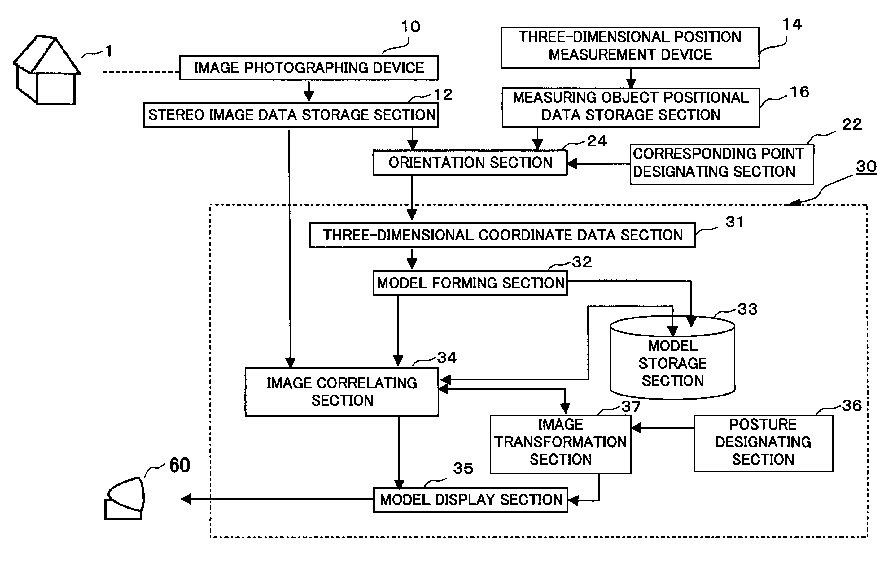
The invention is a three-dimensional image display apparatus and method that allows for the creation of a model of a measuring object using stereo images and the transformation of the model based on the position and tilt of the stereo images. The apparatus includes an orientation section that finds corresponding points in the stereo images, a three-dimensional coordinate data section that obtains coordinate data on the corresponding points, a model forming section that creates a model of the measuring object based on the coordinate data, and an image correlating section that combines the stereo images with the model to create a display with a sense of depth and dimension. The apparatus can also include a posture designating section that allows for the designation of a posture for the measuring object, and a corresponding point designating section that facilitates orientation work. The technical effects of the invention include improved accuracy and efficiency in measuring objects and the ability to create a realistic representation of the object in a pseudo manner.

Problems solved by technology

Therefore, problems have become apparent that it is difficult to correlate 3D data obtained with the three-dimensional position measurement apparatus and the site conditions, and that it is difficult to decide which part of a measuring object is measured in tying the 3D data with image information on the measuring object.
In addition, some people can achieve stereoscopic vision well while others cannot.
That is, there has been a problem that not everyone can always make recognition easily.
The orientation work involves great differences among individuals and thus cannot be performed with ease and accuracy, which has been another problem.

Method used


Image

  • Three-dimensional image display apparatus and method
  • Three-dimensional image display apparatus and method
  • Three-dimensional image display apparatus and method

Examples


first embodiment

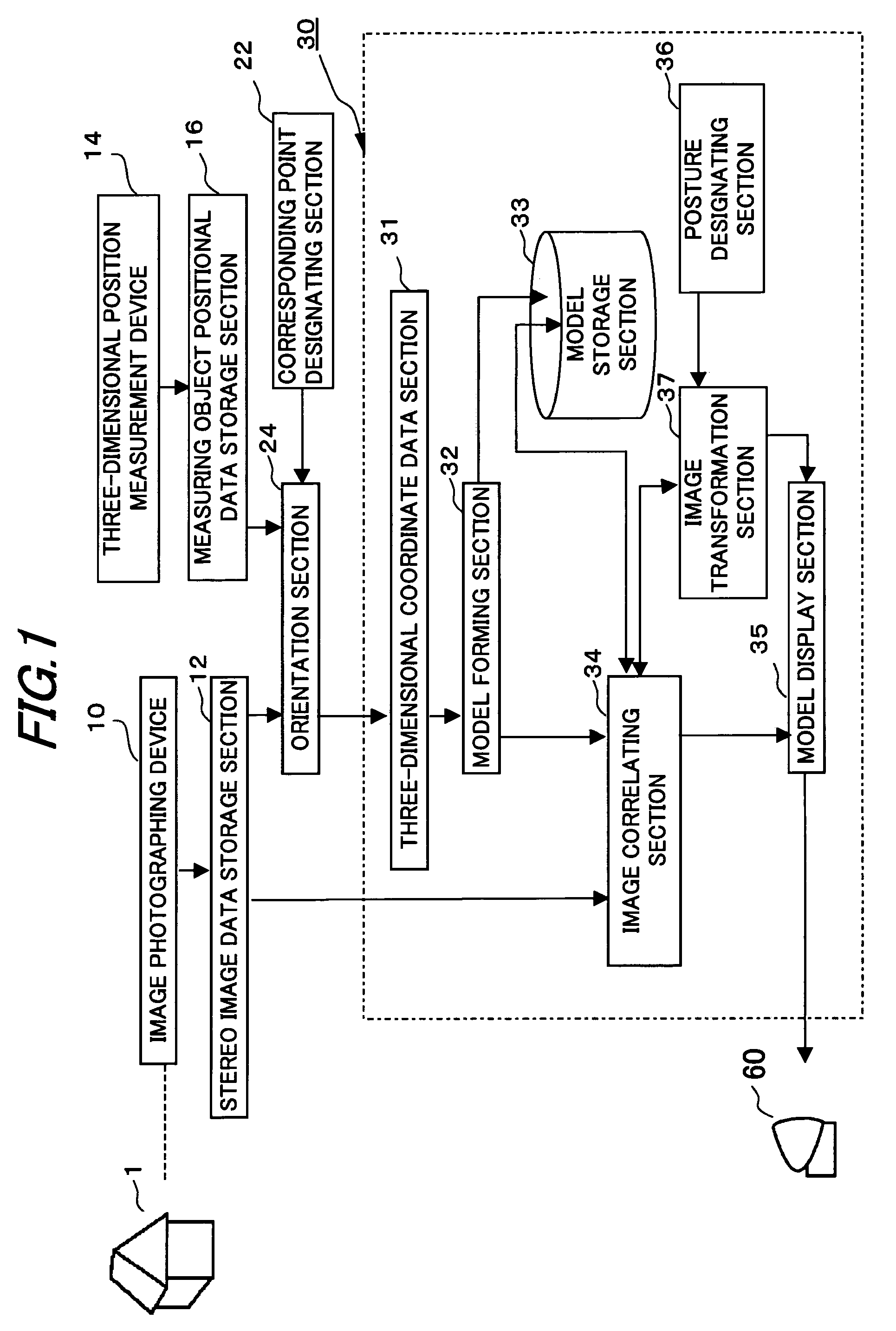
[0081]FIG. 1 is a general constitutional block diagram of the present invention. The present invention includes a stereo image data storage section 12, a measuring object positional data storage section 16, a corresponding point designating section 22, an orientation section 24, a display image forming section 30, and a display device 60, and may be implemented by, for example, a computer and a display device. The measuring object 1 is a tangible substance such as a working object or a manufacturing object. The measuring object 1 may be, for example, a workpiece of various kinds such as architecture, a person, or a landscape. An image photographing device 10 may be, for example, a stereo camera, or a combined device of a general-purpose digital camera and a device for compensating lens aberration between left and right images of the measuring object 1 photographed with the digital camera.

[0082]A three-dimensional position measurement device 14 is an instrument for automatically meas...

second embodiment

[0165]FIG. 20 is a general constitutional block diagram of the present invention. The present invention includes a stereo image data storage section 12, a measuring object positional data storage section 16, a reference point setting section 21, a corresponding point search section 23, an orientation section 24, a corresponding point designating section 25, a display image forming section 30, and a display device 60, and may be implemented by, for example, a computer and a display device. Here, a reference point setting section 21, a corresponding point search section 23, an orientation section 24, and a corresponding point designating section 25 constitute an orientation processing section 20. The measuring object 1 is a tangible substance such as working object or manufacturing object. The measuring object 1 may be, for example, a workpiece of various kinds such as architecture, a person, or a landscape. An image photographing device 10 is intended to obtain a stereo image of the ...

third embodiment

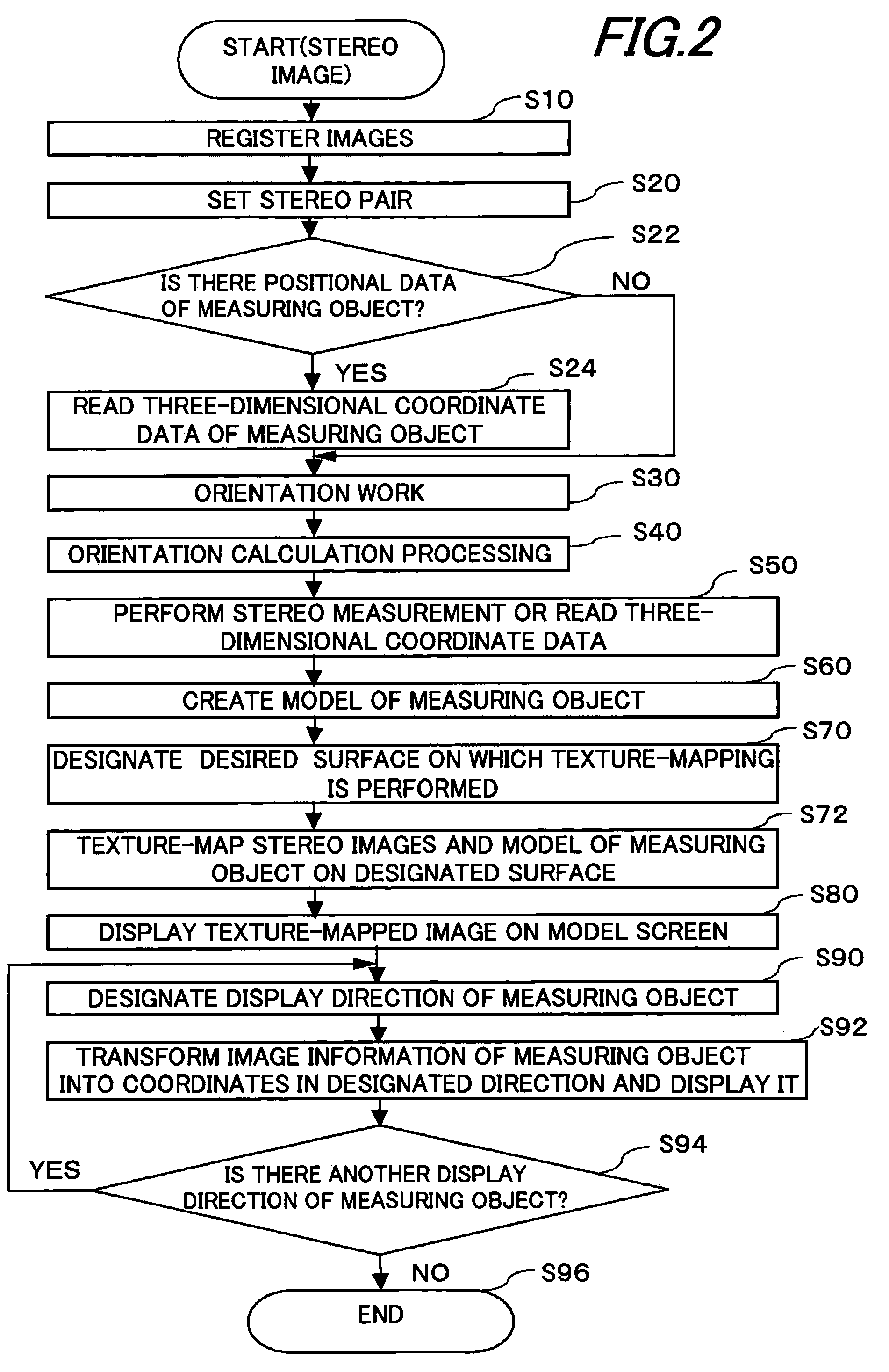
[0194]the present invention is described below with reference to the figures. A three-dimensional image display apparatus of the present embodiment calculates a three-dimensional shape of a measuring object 1 using an image (single photographic image or stereo image) of the measuring object 1 and 3D data obtained externally or through 3D measurement of an entirety of the measuring object 1, to apply texture that produces a stereoscopic effect to a two-dimensional image of the measuring object 1. Here, texture is a term used in the graphics field and so on, representing what is drawn on a surface of a figure to illustrate a pattern and a feel. Photographing the measuring object 1 such that each resulting two-dimensional image includes 3D data (three-dimensional positional data) at six or more points allows orientation of the two-dimensional image by correlating the three-dimensional positional data and the two-dimensional image of the measuring object 1.

[0195]Examples, principles, an...


PUM


Abstract

A three-dimensional image display apparatus is provided that can integrate and visualize 3D measurement data obtained from a stereo image with an image of a measuring object to which stereoscopic texture is applied. The apparatus includes: an orientation section for finding relationship as to corresponding points in a stereo image of a measuring object; a three-dimensional coordinate data section for obtaining three-dimensional coordinate data on the corresponding points of the measuring object; a model forming section for forming a model of the measuring object based on the three-dimensional coordinate data on the corresponding points; an image correlating section for correlating the stereo image of the measuring object stored in the stereo image data storage section and the model formed by the model forming section; and a model display section for displaying an image of the measuring object to which stereoscopic texture is applied.

Description

[0001]This application claims priority to Japan Priority Applications 2003-400754 and 2003-400914, both filed Nov. 28, 2003, and Japan Priority Application 2003-415807, filed Dec. 12, 2003.BACKGROUND OF THE INVENTION[0002]1. Technical Field[0003]The present invention relates to a three-dimensional image display apparatus and method for directly correlating 3D data (three-dimensional shape data) measured on a measuring object and an image (single photographic image or stereo image) of the measuring object, and concurrently displaying the measurement data and the image of the measuring object.[0004]2. Related Art[0005]Methods for obtaining 3D data on a working object or a manufacturing object include an approach of obtaining data with a three-dimensional measurement apparatus (total station), and a stereo image measurement approach of obtaining 3D data by stereo measurement of a stereo image photographed using a measuring object and a comparative calibrated body. The approach using a ...

Claims


Application Information

Patent Timeline
Patent Type & Authority Patents(United States)
IPC IPC(8): H04N13/00G06T7/00G06T15/04G06T17/00
CPCG06T7/0046G06T7/0075G06T17/00G06T15/04G06T2207/10012G06T7/75G06T7/593
Inventor ITO, TADAYUKIOTANI, HITOSHIKOCHI, NOBUO
Owner KK TOPCON
Learn More