Developer material container, image forming unit, and image forming apparatus

a technology of developing material and forming units, which is applied in the direction of electrographic process equipment, instruments, optics, etc., can solve the problems of foreign matter entering the toner cartridg

Active Publication Date: 2010-06-29
OKI ELECTRIC IND CO LTD
View PDF3 Cites 5 Cited by
  • Summary
  • Abstract
  • Description
  • Claims
  • Application Information

AI Technical Summary

Benefits of technology

[0014]The enabling-and-disabling member allows said shutter member to move relative to said holding body when said the developer material container is held with the discharging opening facing upwardly in a gravitational direction, and does not allow said shutter member to move relative to said holding body when the developer material container is held with the discharging opening facing downwardly in the gravitational direction.
[0015]The enabling-and-disabling member couples the shutter member to the holding body when the developer material container is held with the discharging opening facing upwardly in a gravitational direction, and decouples the shutter member from the holding body when the developer material container is held with the discharging opening facing downwardly in the gravitational direction.

Problems solved by technology

Therefore, opening the shutter inadvertently may allow foreign matter to enter the toner cartridge.

Method used


Image

  • Developer material container, image forming unit, and image forming apparatus
  • Developer material container, image forming unit, and image forming apparatus
  • Developer material container, image forming unit, and image forming apparatus

Examples


first embodiment

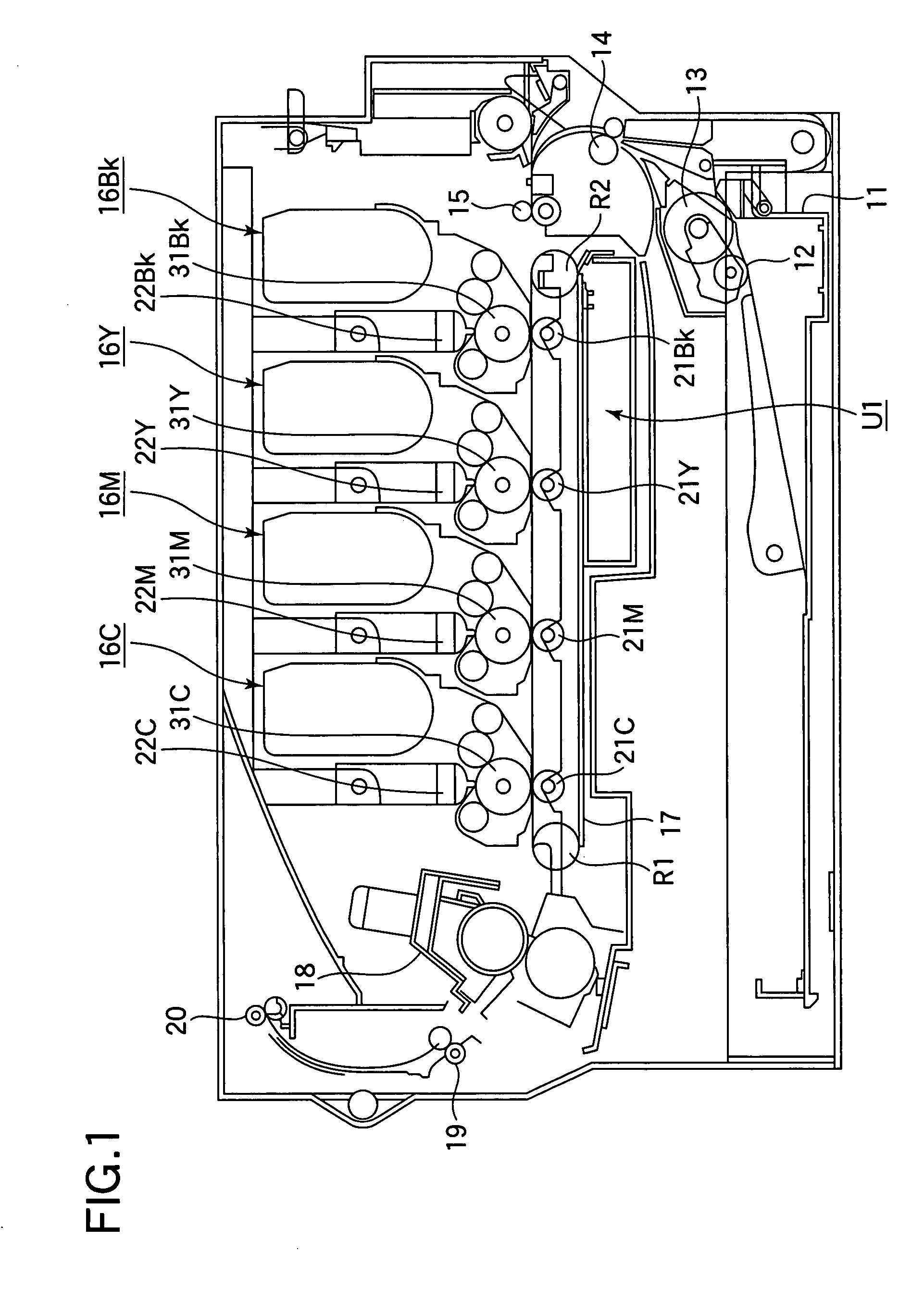
[0051]FIG. 1 illustrates a general configuration of a printer of a first embodiment.

[0052]Referring to FIG. 1, a paper cassette 11 is located at a lower portion of the printer. The paper cassette 11 holds paper (not shown) as a recording medium. A paper feeding mechanism is disposed adjacent a forward end of the paper cassette 11, and feeds the paper on a page-by-page basis. The paper feeding mechanism includes a feed roller 12 and a separator roller 13. The paper fed by the paper feeding mechanism is then advanced to a transporting roller 14 disposed above the paper feeding mechanism. The paper is further transported by another transporting roller 15 to image forming units 16BK (black), 16Y (yellow), 16M (magenta), and 16C (cyan) that form black, yellow, magenta, and cyan images, respectively.

[0053]The image forming units 16BK, 16Y, 16M, and 16C include photoconductive drums 31BK (black), 31Y (yellow), 31M (magenta) and 31C (cyan), respectively. LED printheads (exposing units) 22BK...

second embodiment

[0079]Elements similar to those of the first embodiment have been given the same reference numerals and their description is omitted.

[0080]FIG. 10 is an exploded perspective view of a toner cartridge 41 of a second embodiment. FIG. 11 is a perspective view illustrating a shutter 62 of the second embodiment.

[0081]The shutter 62 includes an arcuate wall 62c that closes the toner outlet 44 and an opening 62a that may be brought into alignment with the toner outlet 44. A sealing member 62d is bonded to the outer convex circumferential surface of the arcuate wall 62c, thereby preventing the fresh toner from leaking out of the toner cartridge 41. An operation lever 63 fits over a cylindrical portion 62b formed at a longitudinal end portion of the shutter 62, and is slidable relative to the cylindrical portion 62b. A stopper 46 is provided on the casing 43. The operation lever 63 is supported by a support (not shown) formed on the casing 43 so that the operation lever 63 will not drop from...

third embodiment

[0090]Elements similar to those of the first and second embodiments have been given the same reference numerals and their description is omitted.

[0091]FIG. 16 is a cross-sectional view illustrating a pertinent portion of a toner cartridge of a third embodiment. FIG. 17 is a cross-sectional view illustrating a pertinent portion of the toner cartridge 41.

[0092]A shutter 62 includes an arcuate wall 62c and a cylindrical portion 62b. When the operation lever 63 is operated to a closing position, the arcuate wall 62c closes the toner outlet 44. An inner recess 206 is formed in the cylindrical portion 62b at a position where the inner recess 206 is lowest in a gravitational direction when the shutter 62 completely closes the toner outlet 44. The operation lever 63 includes an inner circumferential surface that slides on the cylindrical portion 62b, and an outer recess 207 formed in the inner circumferential surface. When the operation lever 63 is operated to the closing position, the oute...


PUM


Abstract

A developer material container includes a holding body, a shutter member movably, an operation member, and coupling member. The holding body holds developer therein and includes a developer outlet. The shutter member movably is assembled to the holding body. The shutter member is movable either to an opening position where the shutter member opens the developer outlet or to a closing position where the shutter member closes the developer outlet. The operation member is operated to move the shutter to either the opening position or to the closing position. Depending on the orientation of the discharging opening, an enabling-and-disabling member allows or does not allow the operation member to move the shutter relative to the holding body.

Description

BACKGROUND OF THE INVENTION[0001]1. Field of the Invention[0002]The present invention relates to a developer material container, an image forming unit, and an image forming apparatus.[0003]2. Description of the Related Art[0004]Among conventional image forming apparatuses are electrophotographic printers, copying machines, facsimile machines, and multi function peripheral (MFP) devices capable of various tasks such as printing, faxing, and copying. For example, a printer includes image forming units each of which includes, for example, a photoconductive drum, a charging unit, an exposing unit, and a developing unit. The charging unit charges the surface of the photoconductive drum uniformly. The exposing unit includes an LED print head that illuminates the charged surface of the photoconductive drum to form an electrostatic latent image. The developing unit develops the electrostatic latent image with toner into a toner image. A transfer roller transfers the toner image onto paper. ...

Claims


Application Information

Patent Timeline
Patent Type & Authority Patents(United States)
IPC IPC(8): G03G15/08
CPCG03G15/0855G03G15/0865G03G15/0886G03G2215/067G03G2215/0692
Inventor KOIDO, SIGENORI
Owner OKI ELECTRIC IND CO LTD
Why Eureka
Try Eureka