Head assignment modeling and simulation

a head assignment and simulation technology, applied in the field of tape and fiber placement systems, can solve the problem that existing composite part programming systems do not have the capacity to efficiently program composite material application machines with multiple composite material application heads

Active Publication Date: 2010-06-29
THE BOEING CO
View PDF9 Cites 36 Cited by
  • Summary
  • Abstract
  • Description
  • Claims
  • Application Information

AI Technical Summary

Problems solved by technology

However, existing composite part programming systems do not have the capacity to efficiently program a composite material application machine with multiple composite material application heads to form a variety of composite parts.

Method used


Image

  • Head assignment modeling and simulation
  • Head assignment modeling and simulation
  • Head assignment modeling and simulation

Examples


Embodiment Construction

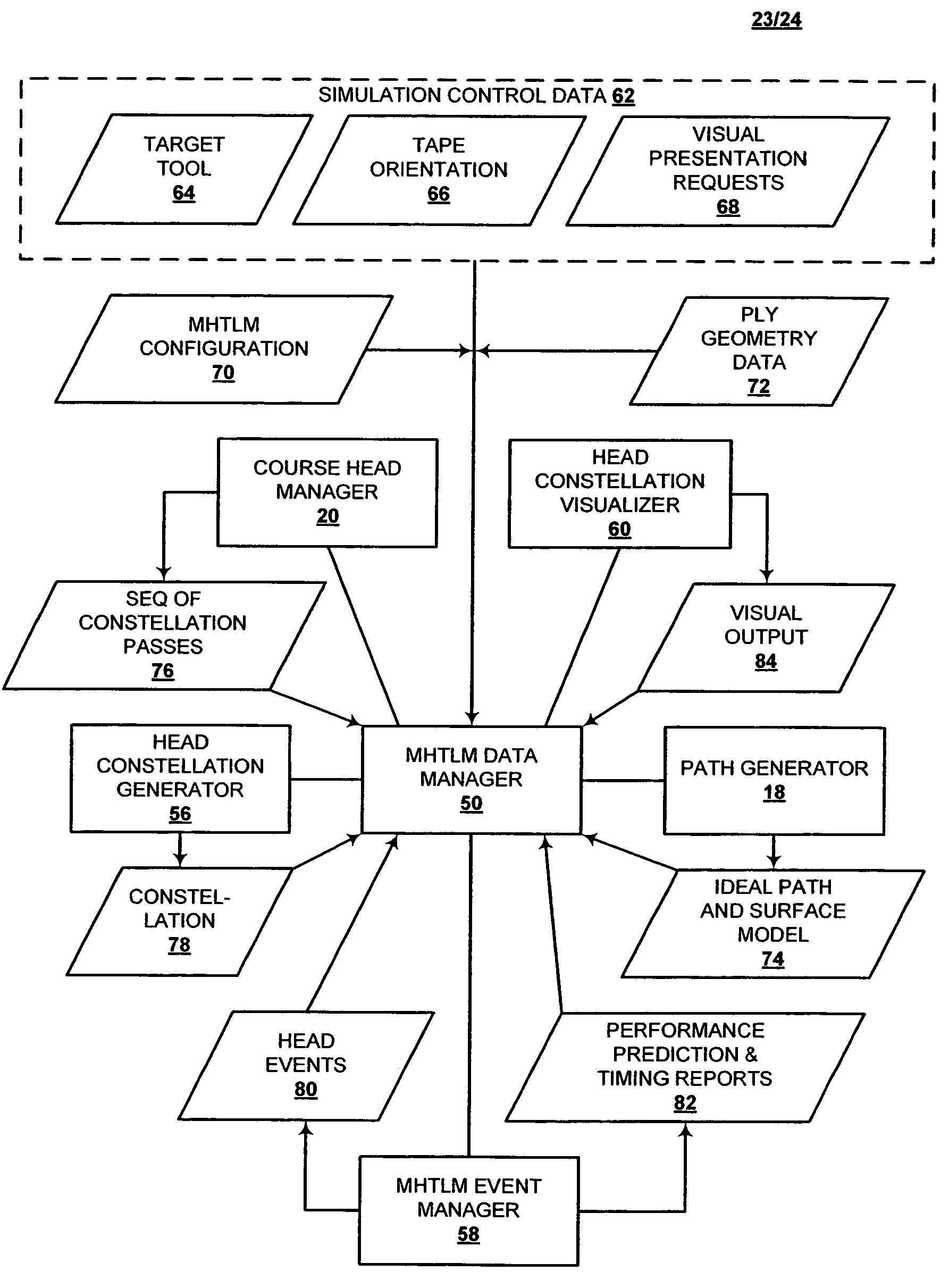
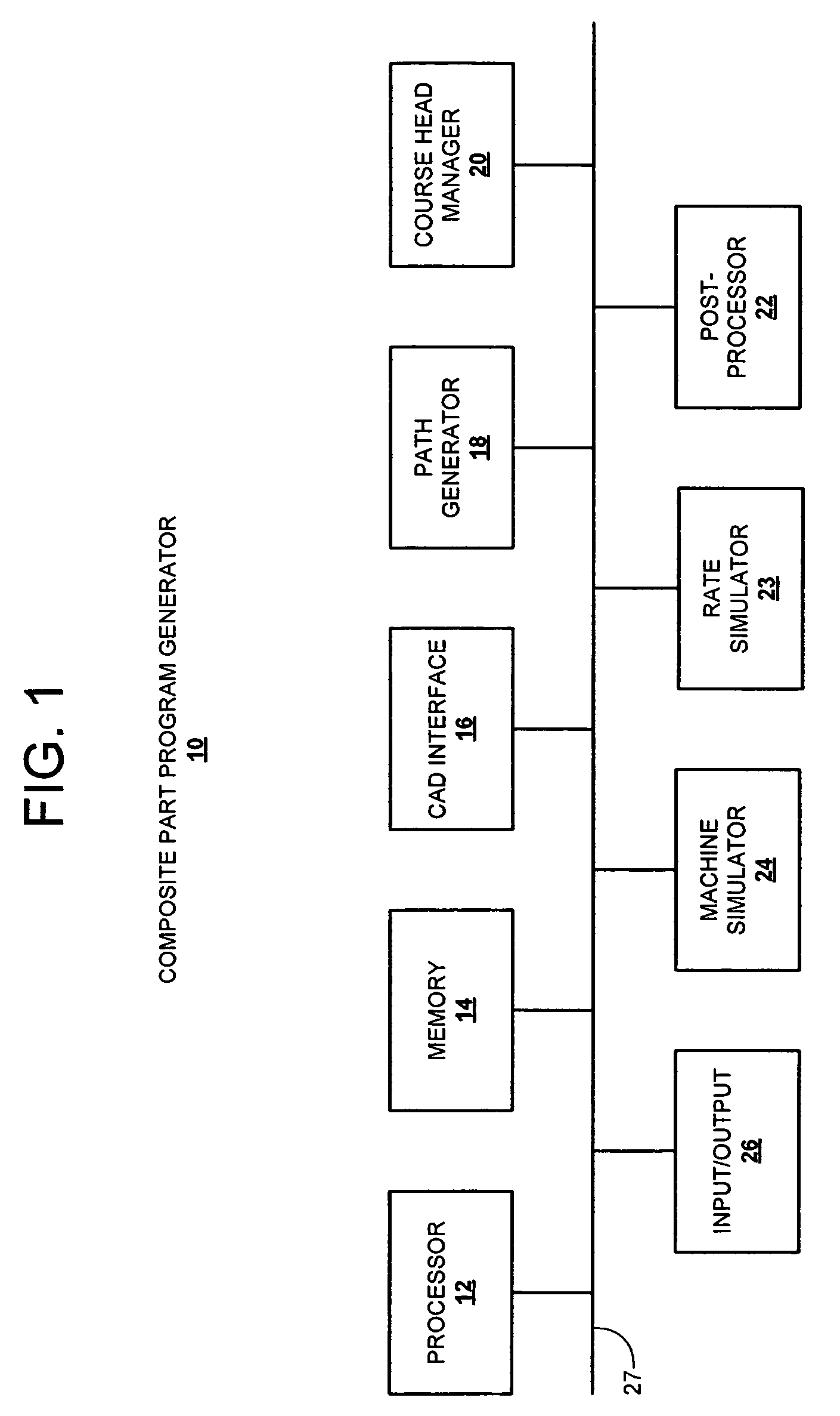
[0022]An embodiment in accordance with the present invention provides a composite part program generator, which can include a computer-aided design (CAD) system interface, a path generator, a course head manager, a post-processor and a machine simulator. The composite part program generator is capable of producing composite part programs for a wide variety of large, complex composite parts, including relatively flat, contoured, or generally cylindrical composite parts. This programming method can reduce the labor required to produce a composite part program for a multihead composite material application machine by an order of magnitude with respect to manual or existing automated programming methods.

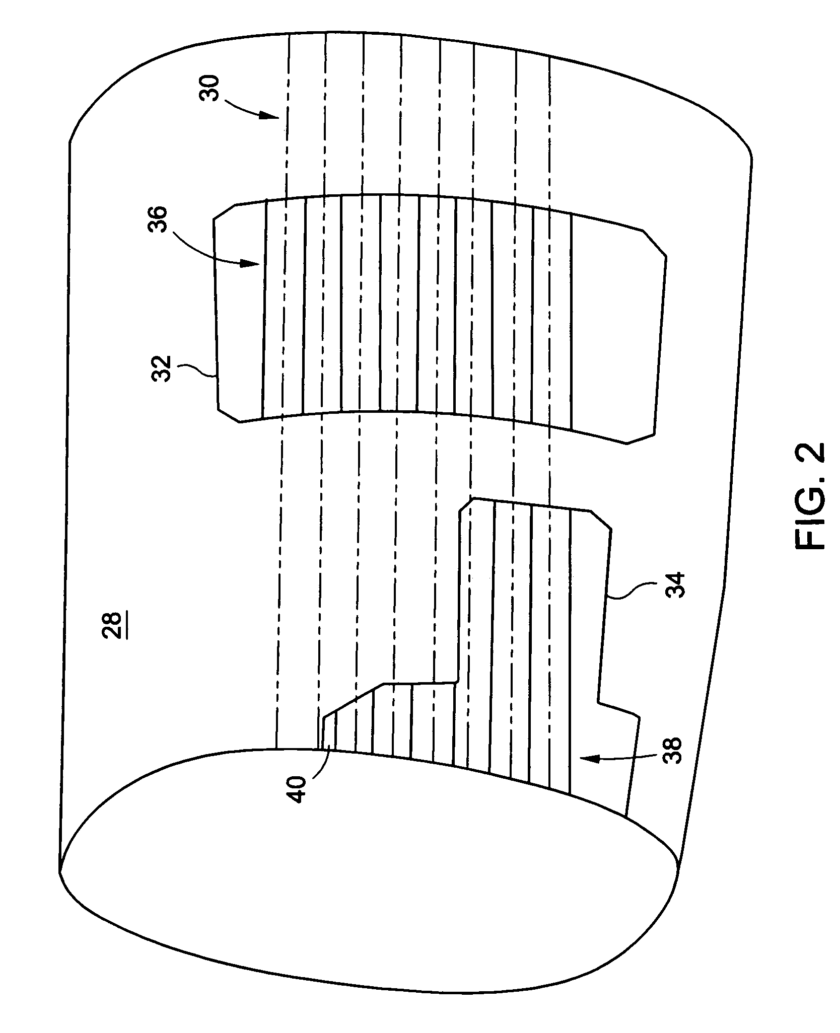
[0023]The composite part program generator can produce, for example, composite part programs for use with computer-numerical control (CNC) composite material application machines having a single composite material application head, such as existing composite tape-laying machines and auto...


PUM

PropertyMeasurementUnit
widthaaaaaaaaaa
widthaaaaaaaaaa
structuresaaaaaaaaaa

Abstract

To model head assignments for a multihead composite material application machine having a set of heads, a ply geometry for a composite part is received and a configuration for the multihead composite material application machine is received. In addition, a constellation of head locations is generated in response to the ply geometry and the configuration for the multihead composite material application machine. Furthermore, a head location of the constellation of head locations is assigned to a corresponding head of the set of heads and a graphical model of the multihead composite material application machine applying the composite material upon the composite part is generated in response to the assigned head locations.

Description

FIELD OF THE INVENTION[0001]The present invention relates generally to tape and fiber placement systems. More particularly, the present invention relates to a method of head assignment modeling and simulation in a computer-numerical-controlled, composite tape lamination and fiber placement device.BACKGROUND OF THE INVENTION[0002]Composite materials have been used increasingly in a variety of industries, including the automotive, marine and aerospace industries. In some instances, composite parts can be formed using automated composite material application machines, such as composite tape lamination machines or composite fiber placement machines.[0003]Some conventional composite material application machines, for example, a flat tape lamination machine (FTLM) or a contoured tape lamination machine (CTLM), produce flat or gently contoured composite parts by laying relatively wide strips of composite tape onto generally horizontal or vertical tooling surfaces, such as a mandrel. Other ...

Claims


Application Information

Patent Timeline
Patent Type & Authority Patents(United States)
IPC IPC(8): G06G7/48
CPCG05B19/40938B29C70/386Y02P90/02
Inventor TANG, WEI-PAISU, TIMOTHY F.
Owner THE BOEING CO
Why Eureka
Try Eureka