
Determining in-situ the relation between seismic velocity and state of stress in an underground formation

a technology of stress and seismic velocity, applied in seismology for waterlogging, instruments, reradiation, etc., can solve the problem of complex task of determining long-distance seismic velocity from sonic measurements

Active Publication Date: 2010-07-06
SHELL USA INC
View PDF23 Cites 8 Cited by
  • Summary
  • Abstract
  • Description
  • Claims
  • Application Information

AI Technical Summary

Problems solved by technology

Deriving long-distance seismic velocities from sonic measurements is a very complicated task.

Method used


Image

  • Determining in-situ the relation between seismic velocity and state of stress in an underground formation
  • Determining in-situ the relation between seismic velocity and state of stress in an underground formation

Examples


Embodiment Construction

[0016]Described is a method of determining in-situ a relation between the seismic velocity and the state of stress in an underground formation located under a surface subjected to time-changing surface loading conditions.

[0017]An example of a surface loading condition that changes with time is the tide of the sea above the sea floor, wherein the sea floor is the surface below which the underground formation is located. Another example is a shifting sand dune in a desert.

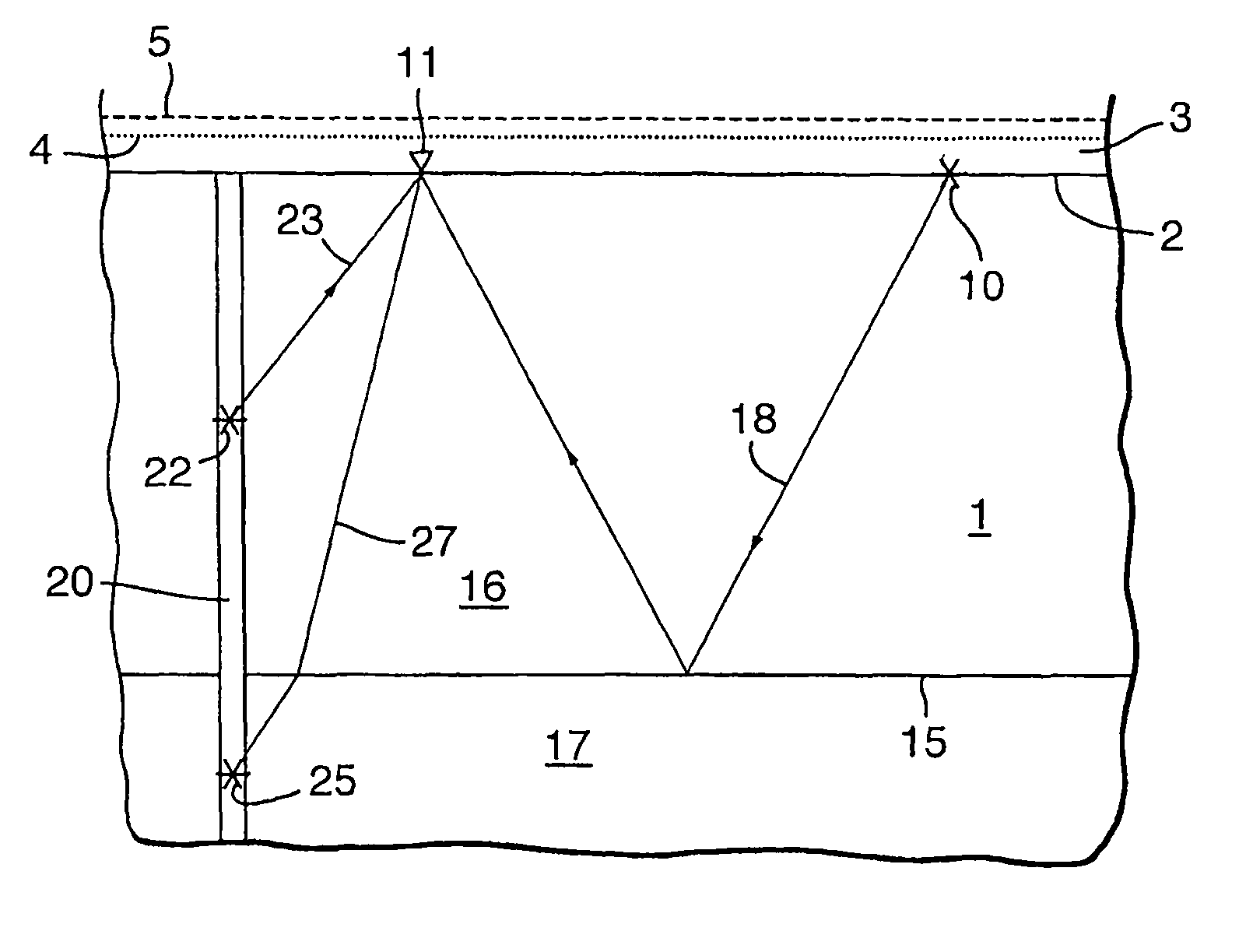
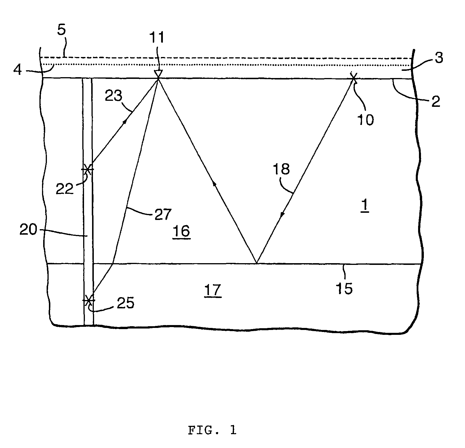
[0018]The invention will now be described by way of example in more detail with reference to the accompanying drawing. The drawing shows schematically and not to scale a cross-section of a homogeneous underground formation illustrating paths of seismic waves. The drawing illustrates a homogeneous underground formation 1 is located below a surface 2, which is in this case a sea floor covered by a sea 3. The sea 3 has two tidal levels, a low tide shown by the dotted line 4 and a high tide shown by the dashed line 5. In...


PUM


Abstract

A method of determining in-situ a relation between the seismic velocity and the state of stress in an underground formation located under a surface subjected to time-changing surface loading conditions. A relation is selected between the seismic velocity and the state of stress containing at least one unknown parameter. A seismic source is arranged at surface or in a borehole penetrating the underground formation, and a seismic receiver is arranged at a distance from the seismic source at surface or in a second borehole. At two different times the seismic velocity of the formation along a path from the seismic source to the seismic receiver is determined. The difference in surface loading conditions at the two times is converted in a difference in states of stress in the underground formation. The unknown parameter(s) are calculated to obtain the relation between the seismic velocity and the state of stress in the underground formation.

Description

[0001]The present application claims priority on European Patent Application 04253932.0 filed 30 Jun. 2004.FIELD OF THE INVENTION[0002]The present invention relates to determining the relation between the seismic velocity and the state of stress in an underground formation. The relation is used in producing a stress dependent seismic survey based on geomechanical modelling of an underground formation.BACKGROUND OF THE INVENTION[0003]Time-lapse seismic is used to detect changes in a reservoir that occur between a first survey and a second survey after a predetermined time. The time between two successive surveys is so determined that a change in the underground formation can be detected. In many instances time-lapse seismic surveying is done to study changes in an underground reservoir.[0004]An example of time-lapse seismic monitoring is described in U.S. Pat. No. 4,969,130. This publication discloses monitoring the fluid contents of a petroleum reservoir, wherein a reservoir model i...

Claims


Application Information

Patent Timeline
Patent Type & Authority Patents(United States)
IPC IPC(8): G06F19/00G01V1/30
CPCG01V1/30
Inventor MOLENAAR, MENNO MATHIEU
Owner SHELL USA INC
Learn More