Atomic command retry in a data storage system

ommand technology, applied in the field ofatomic command retry in a data storage system, can solve problems such as further errors

Active Publication Date: 2010-07-06
EMC IP HLDG CO LLC
View PDF7 Cites 7 Cited by
  • Summary
  • Abstract
  • Description
  • Claims
  • Application Information

AI Technical Summary

Problems solved by technology

This means that, during the read-modify-write command, some of the data may have been incompletely modified and written back to the memory location.
If the latter command were to be issued to

Method used


Image

  • Atomic command retry in a data storage system
  • Atomic command retry in a data storage system
  • Atomic command retry in a data storage system

Examples


Embodiment Construction

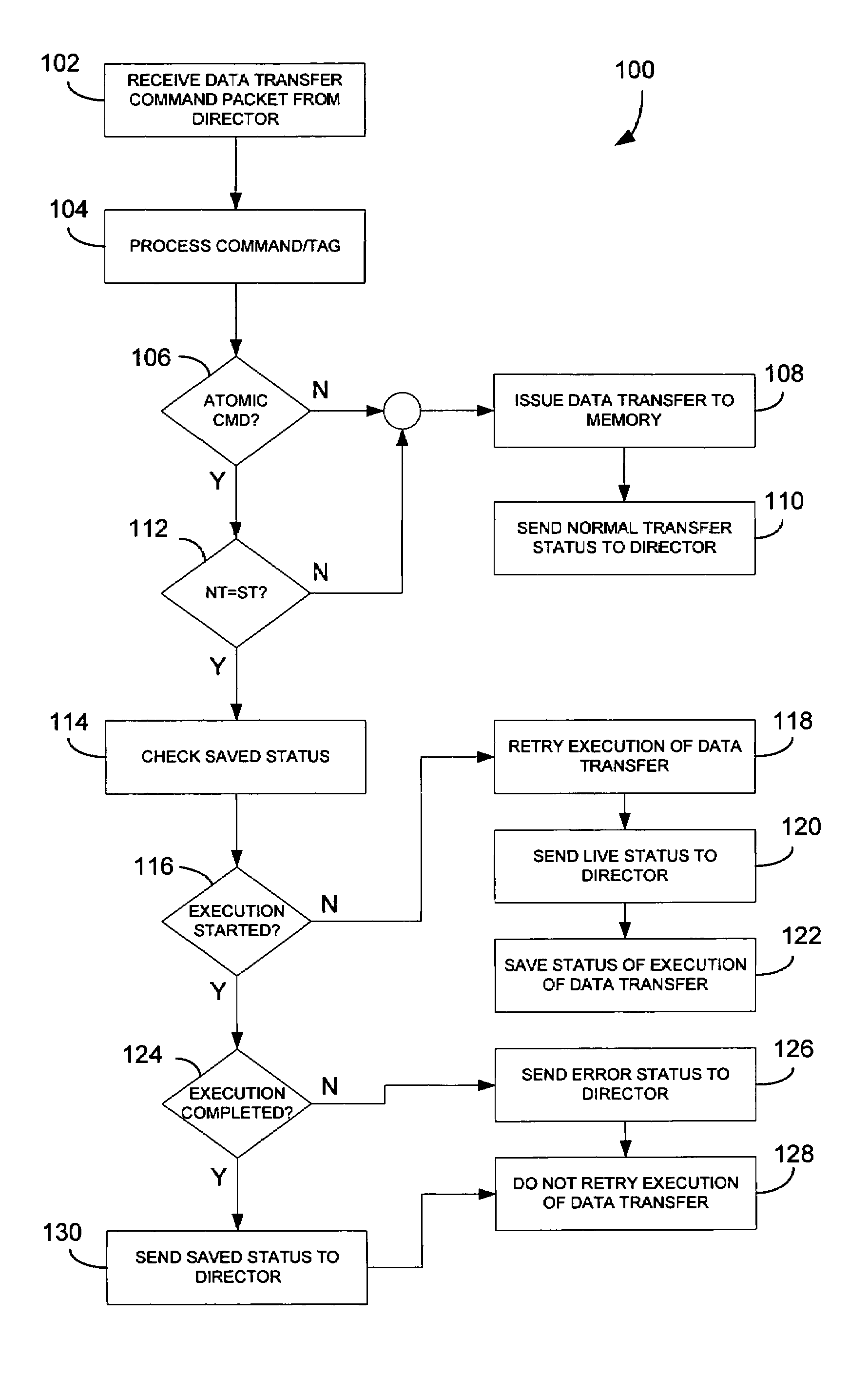
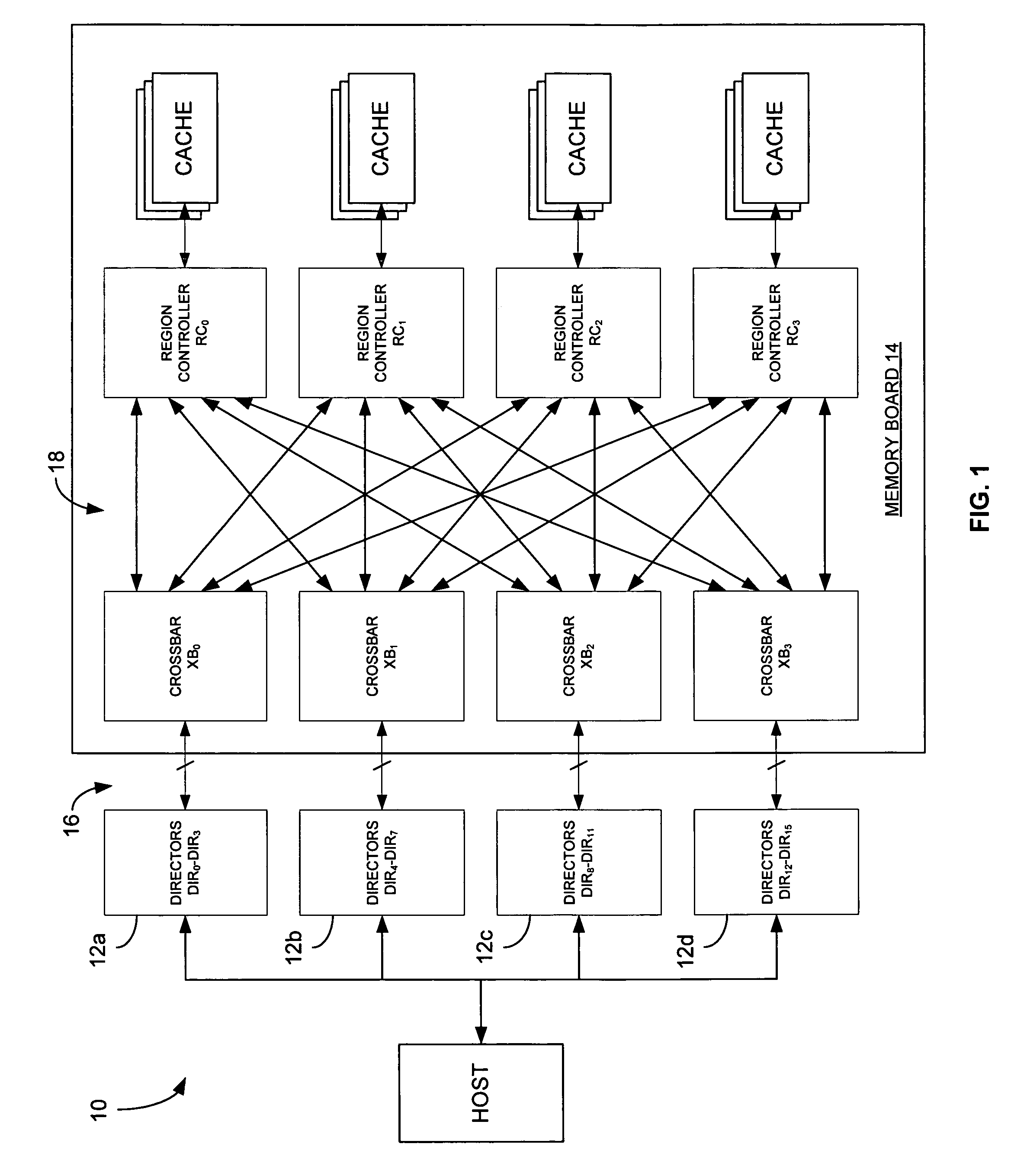
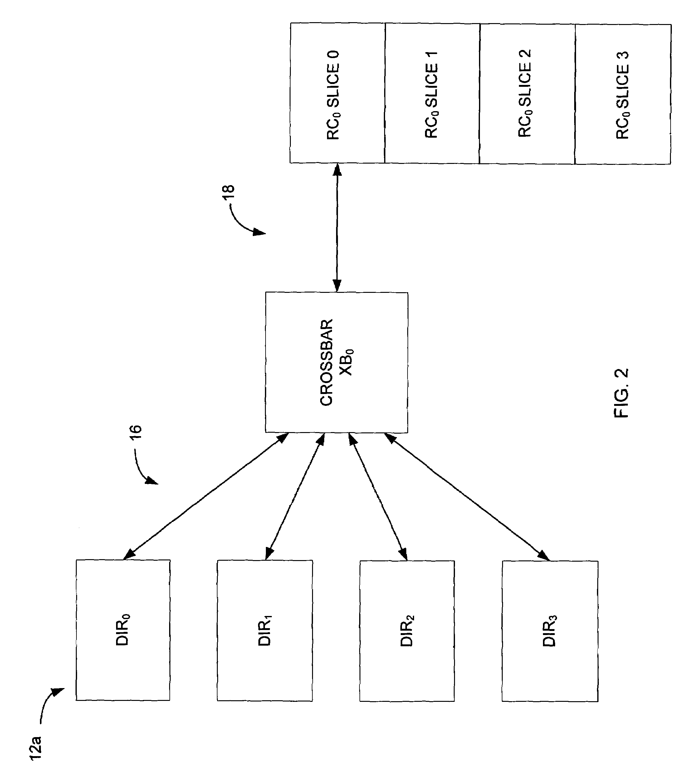
[0017]FIG. 1 is a schematic block diagram of the data command transmission system 10 of the present invention. As shown in the figure, the system 10 includes a plurality of director groups 12a-12d and a memory board 14. Similar to the system of the '933 patent, director groups 12a-12d include directors DIR0-DIR3; DIR4-DIR7; DIR8-DIR11; and DIR9-DIR12, respectively, that are coupled to crossbar switches XB0, XB1, XB2 and XB3, respectively, via UM / XB link 16. Memory board 14 also includes region controllers RC0, RC1, RC2 and RC3, each of which being coupled to a respective cache region. Each of the crossbar switches XB0, XB1, XB2 and XB3 are coupled to each of the region controllers RC0, RC1, RC2 and RC3 via XB / RC link 18. The directors 12a-12d of system 10 may be either a front-end directors or a back-end directors.

[0018]In operation, the host will send a data transfer command to one of the directors, which will transmit the command to its associated crossbar via the UM / XB link 16. T...


PUM


Abstract

A data transfer retry method includes:
    • A. receiving a particular atomic data transfer command from a director;
    • B. processing identification information associated with the particular atomic data transfer command;
    • C. comparing the identification information associated with the particular atomic data transfer command to identification information of a previous atomic data transfer command received from the director;
    • D. determining that the particular atomic data transfer command is a retry command of the previous atomic data transfer command received from the director;
    • E. determining a status of the execution of the previous atomic data transfer command received from the director; and
    • F. processing the particular atomic data transfer command based on the status of the execution of the previous atomic data transfer command determined in Step E.

Description

FIELD OF THE INVENTION[0001]The present invention is generally directed to atomic command retry in a data storage system, and more particularly to a method and system in which all failed data transfer commands, including atomic commands, between a host and memory of the data storage system are retried.BACKGROUND OF THE INVENTION[0002]Network computer systems generally include a plurality of geographically separated or distributed computer nodes that are configured to communicate with each other via, and are interconnected by, one or more network communications media. One conventional type of network computer system includes a network storage subsystem that is configured to provide a centralized location in the network at which to store, and from which to retrieve data. Advantageously, by using such a storage subsystem in the network, many of the network's data storage management and control functions may be centralized at the subsystem, instead of being distributed among the network...

Claims


Application Information

Patent Timeline
IPC IPC(8): G06F3/00
CPCG06F11/1443
Inventor PORAT, OFERAVAKIAN, ARMENDAIGLE, MICHAELSCHARLACH, PAUL
Owner EMC IP HLDG CO LLC
Why Eureka
Try Eureka