Rope tensioning device

a tensioning device and rope technology, applied in the field of rope tensioning devices, can solve the problems of time-consuming, difficult to teach, and complicated knots used by those with experience, and achieve the effects of reducing the risk of failure if not properly tied, reducing the risk of failure, and reducing the time required to tie knots

Inactive Publication Date: 2010-07-13
HOWARD MICHAEL CHRISTOPHER
View PDF12 Cites 14 Cited by
  • Summary
  • Abstract
  • Description
  • Claims
  • Application Information

AI Technical Summary

Benefits of technology

[0013]clamp means,wherein the clamp means are adapted to grip rope inserted into the device allowing it to be pulled in a tightening direction to tension the rope, the clamp means being adapted to prevent the rope pulling in a reverse direction.
[0018]In an alternative construction, the anchoring means may comprise a peg projecting from the front face of the elongate base. The peg is preferably located between the lever arm and the hook at the first end of the base. The peg has a head and a throat around which rope is wrapped whereby the head prevents the rope from disengaging the peg. The head may be angled away from the first hook at the first end to improve anchoring.
[0028]tightening the rope by pulling it so that the clamp prevents the rope moving in the reverse direction.
[0029]The clamp may be a pivoting lever having one end biased towards the front face. The lever preferably prevents rope moving in the reverse direction by gripping the rope with teeth on the lever end, but allows the rope to move in a tightening direction.

Problems solved by technology

Even so, knots used by those experienced can be quite complicated to tie and difficult to teach.
While effective in fastening rope around a load there is a danger of failure if not tied properly.
Furthermore, to tie these kinds of knots is time consuming and if the knots are over-tightened even more time is required to release them.
Elastic cords usually have a shortened life due to the constant stretching to which they are subjected.
Generally, the conditions of use of tying ropes about a load are quite harsh and not suitable for elastic cords.
Buckled straps work well but the buckles are usually attached to the straps and cannot be used on a separate strap or with any kind of rope that is not sufficiently flat to thread through the buckle.
Because the buckles are attached to the straps damage to the load or vehicle may occur when throwing the strap over the load and vehicle to secure it to the vehicle's underside.
It often happens that the user becomes frustrated with the buckles and cuts these off to continue to use the strap as a length of rope.
Aside from having the above described drawbacks of the buckled strap, the winching strap is a complex system that may involve springs, gears and other moving parts making it costly to manufacture, more likely to fail and difficult to use.

Method used


Image

  • Rope tensioning device
  • Rope tensioning device
  • Rope tensioning device

Examples


first embodiment

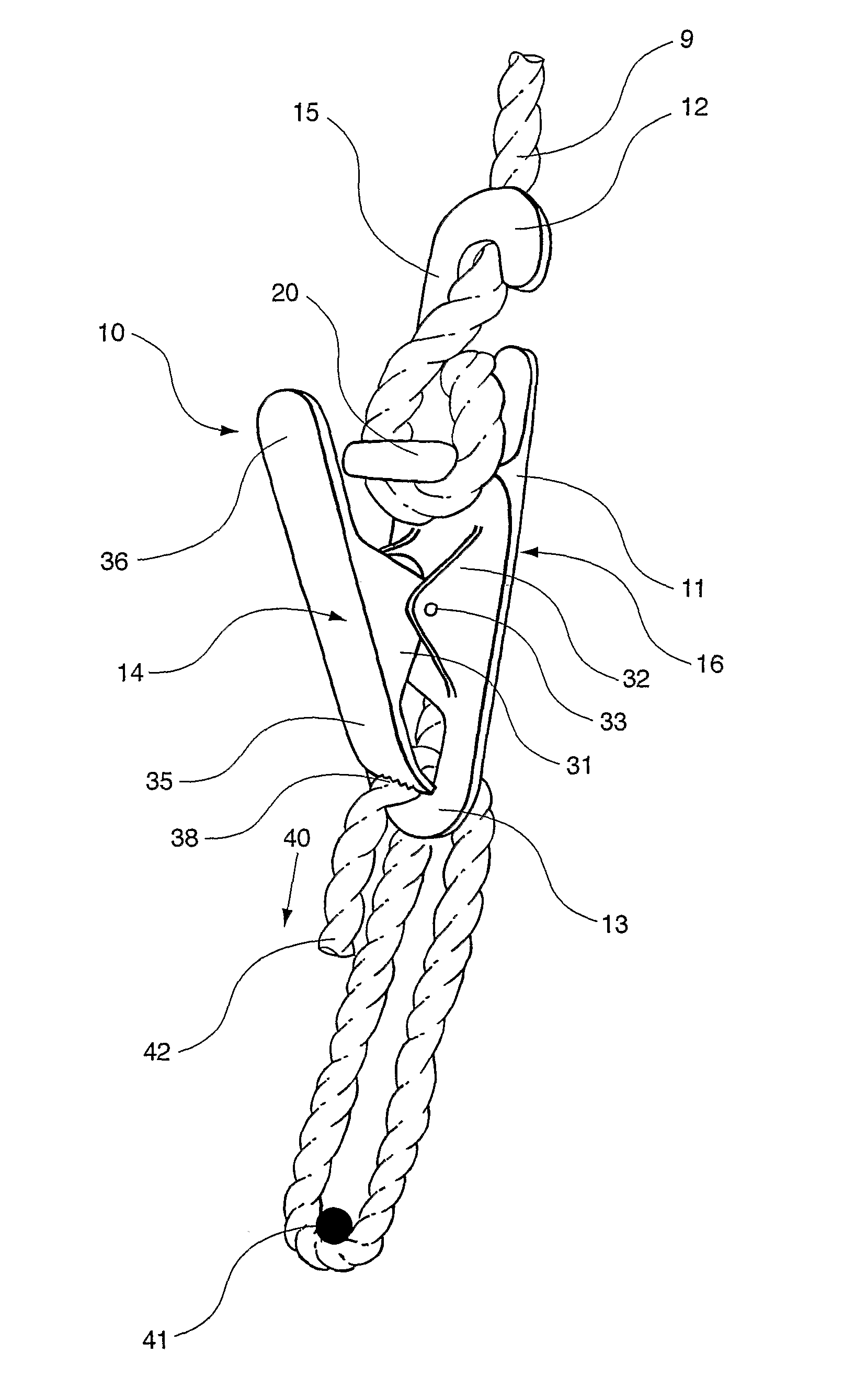
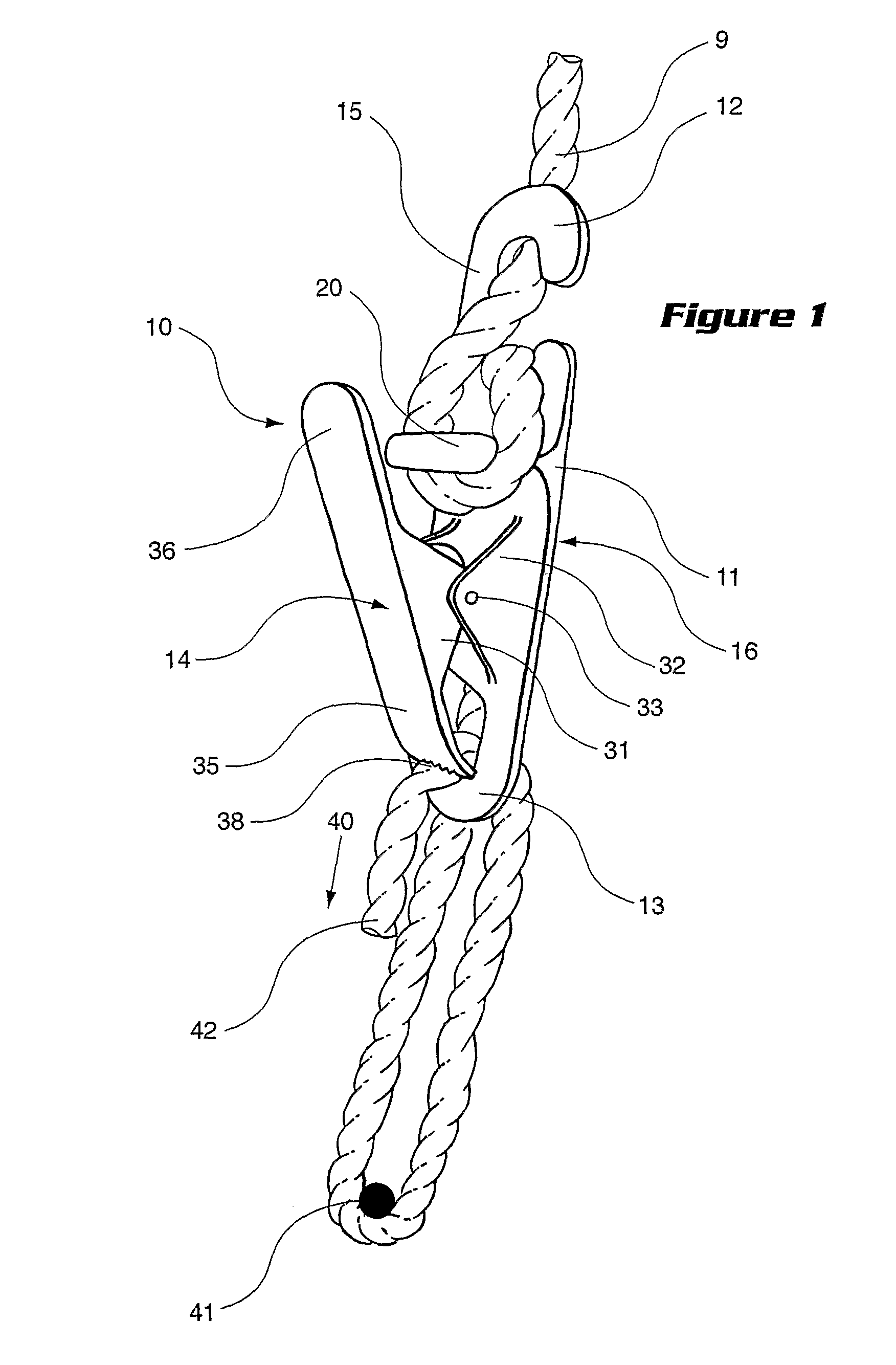
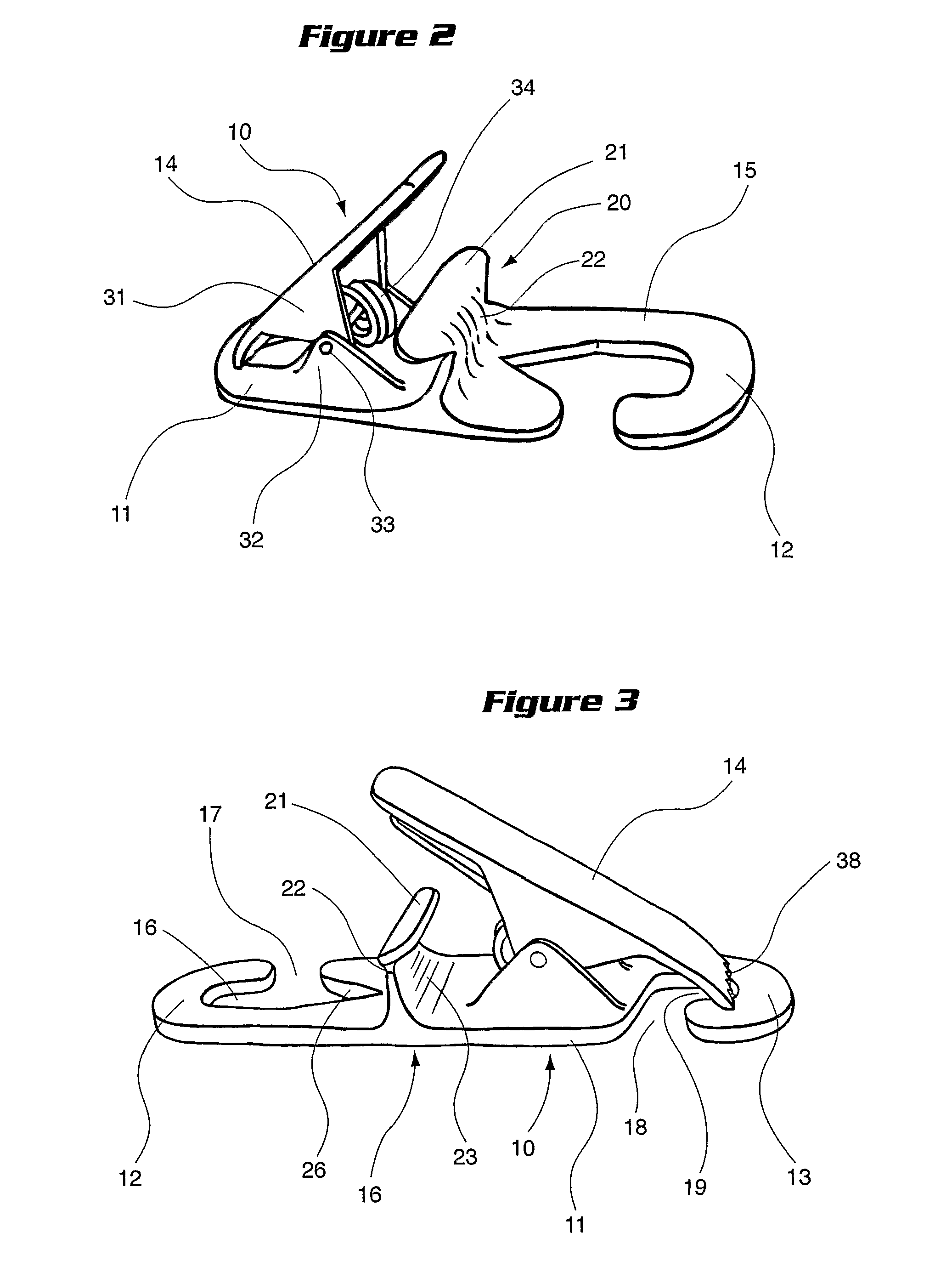
[0134]The first embodiment, illustrated in FIGS. 1 to 3 and 6, comprises an anchoring means in the form a peg 20 located between the first hook end 12 and the lever arm 14. The peg 20 projects outwardly from the front face 15 and includes a head 21 and a throat 22. Rope is adapted to be wrapped around the peg 20, and specifically the throat 22, to hold the rope to the device 10 in a secure manner. Head 21, being larger than the throat 22, ensures the rope is captured between the head 21 and front face 15 thereby preventing escape.

[0135]To further improve the effectiveness of the peg 20 to restrain a loop of rope, the head 21 of the peg 20 is angled away from the first hooked end 12 and creates a concave face 23 against which the rope loop is held.

[0136]The hooks at the hooked ends face opposite directions.

second embodiment

[0137]FIGS. 4 to 6 illustrate the anchoring means in the form of a notch 25. The device's hold on the rope is increased by creating a loop by winding rope around notch 25 and the base of first hooked end 12, which is provided with a V-shaped wedge 26. This prevents the rope sliding out of the hooked end. The notch 25 slants in a parallel direction to the slanting Vshaped wedge 26 to also create a wedge 27 in notch 25 preventing escape of the looped rope from the notch.

[0138]Both embodiments are provided with a V-shaped wedge 26 at the first hooked end 12 for capturing the rope inserted into the device.

[0139]In the second embodiments the hooks are facing the same direction.

[0140]The gripping lever arm 14 is pivotably mounted to the front face 15 at approximately mid length of the arm 14. Two downward flanges 31 on the lever arm 14 align in between two upward flanges 32 on the front face 15. A pin 33 extends through all four flanges to provide a pivoting motion of the lever arm 14 rel...


PUM


Abstract

A rope tensioning device includes an elongated base having a first hooked end and a second hooked end, an anchor for anchoring the rope on the device, and a clamp. The clamp is adapted to grip the rope inserted into the device allowing it to be pulled in a tightening direction to tension the rope. The clamp is adapted to prevent the rope pulling in a reverse direction.

Description

FIELD OF THE INVENTION[0001]The invention is a tensioning device for tightening or fastening rope. One non-limiting example of an application for the device is that of fastening rope around a load and tightening the tension on the load.[0002]It is understood that the term ‘rope’ includes any length of cord including twist ropes, straps, multi-strand cords, lashings and the like.BACKGROUND OF THE INVENTION[0003]More often than not, knots and rope tightening devices are used to secure small objects being transported on utility vehicles and vans, or on a large scale to secure cargo and freight transported by trucks, aircrafts, ships, rail vehicles, etc.[0004]Knot tying is the most simple and rudimentary form of securing a length of rope. Even so, knots used by those experienced can be quite complicated to tie and difficult to teach. One example is the “truckie's knot” which is formed by following a rigid sequence loop, twists and turns. While effective in fastening rope around a load t...

Claims


Application Information

Patent Timeline
Patent Type & Authority Patents(United States)
IPC IPC(8): F16G11/10F16G11/00A63B29/02B60P7/08B66D3/10F16G11/14
CPCB60P7/0823B66D3/10F16G11/10F16G11/14A63B29/02Y10T24/3453Y10T24/3449Y10T24/3947Y10T24/3953F16G11/101F16G11/103
Inventor HOWARD, MICHAEL CHRISTOPHER
Owner HOWARD MICHAEL CHRISTOPHER
Why Eureka
Try Eureka