Eureka AIR delivers breakthrough ideas for toughest innovation challenges, trusted by R&D personnel around the world.

Vehicle drive system, power management device, and method for managing power

a technology for driving systems and power management devices, applied in the direction of vehicle sub-unit features, process and machine control, instruments, etc., can solve the problems of low round-trip efficiency of mechanical conversion, power is not transferred to the accessories as efficiently as desired, and the electric motors used to power the accessories under all operating conditions

Inactive Publication Date: 2010-07-13
GM GLOBAL TECH OPERATIONS LLC
View PDF34 Cites 66 Cited by
  • Summary
  • Abstract
  • Description
  • Claims
  • Application Information

AI Technical Summary

Problems solved by technology

A problem associated with current vehicles is that power is not transferred to the accessories as efficiently as desired.
A problem associated with current hybrid vehicles is that the electric motors utilized to power the accessories under all operating conditions.
This is inefficient because of the low round-trip efficiency of converting mechanical energy from the engine to electrical energy, storing the electrical energy in the battery as chemical energy, converting the chemical energy from the battery to electrical energy then back to mechanical energy to drive the accessories.
Additionally, this approach increases the vehicle costs over vehicles having power distribution systems that power accessories by directly transferring rotational power generated by the engine.

Method used


Image

  • Vehicle drive system, power management device, and method for managing power
  • Vehicle drive system, power management device, and method for managing power
  • Vehicle drive system, power management device, and method for managing power

Examples


Embodiment Construction

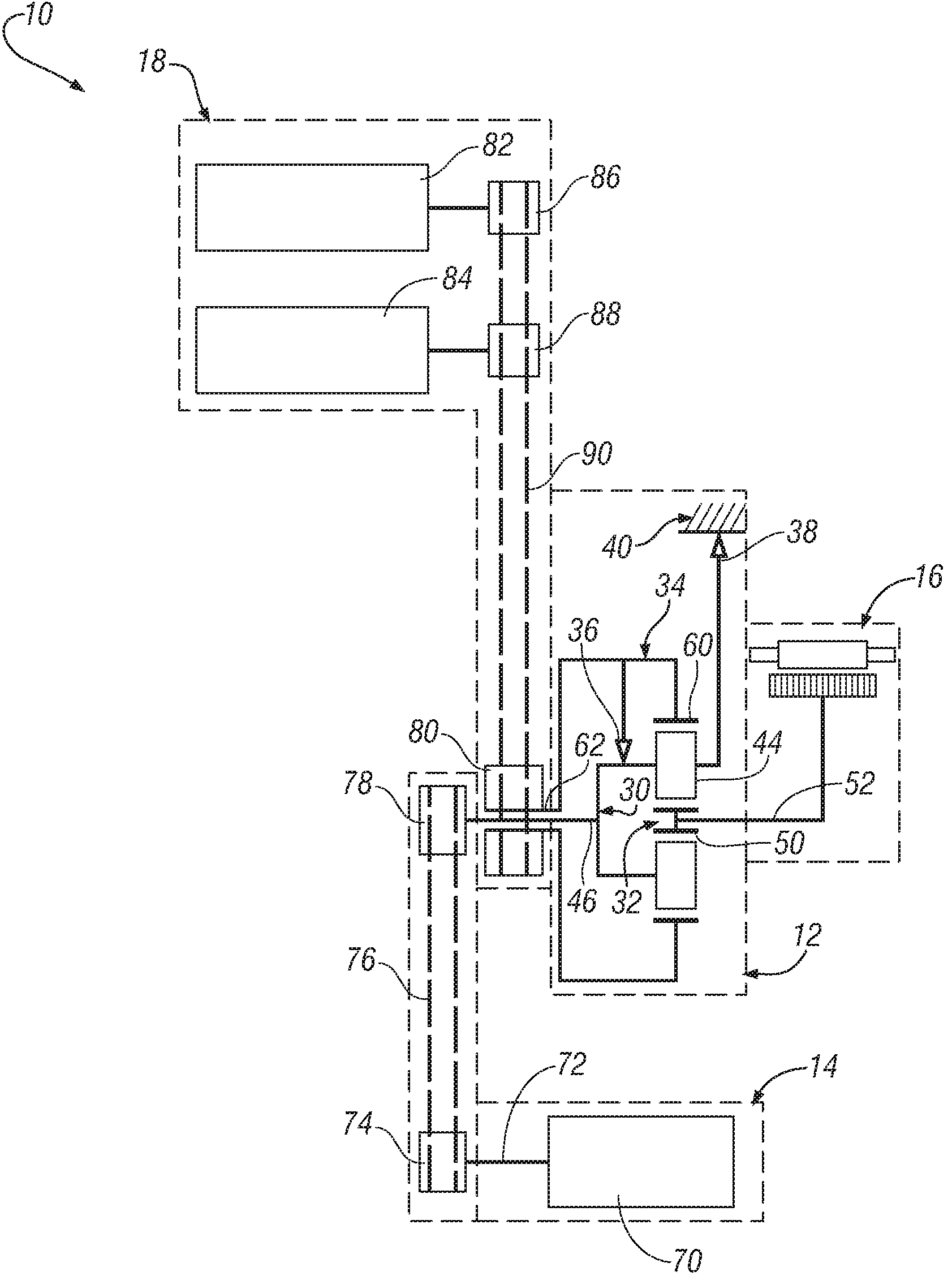
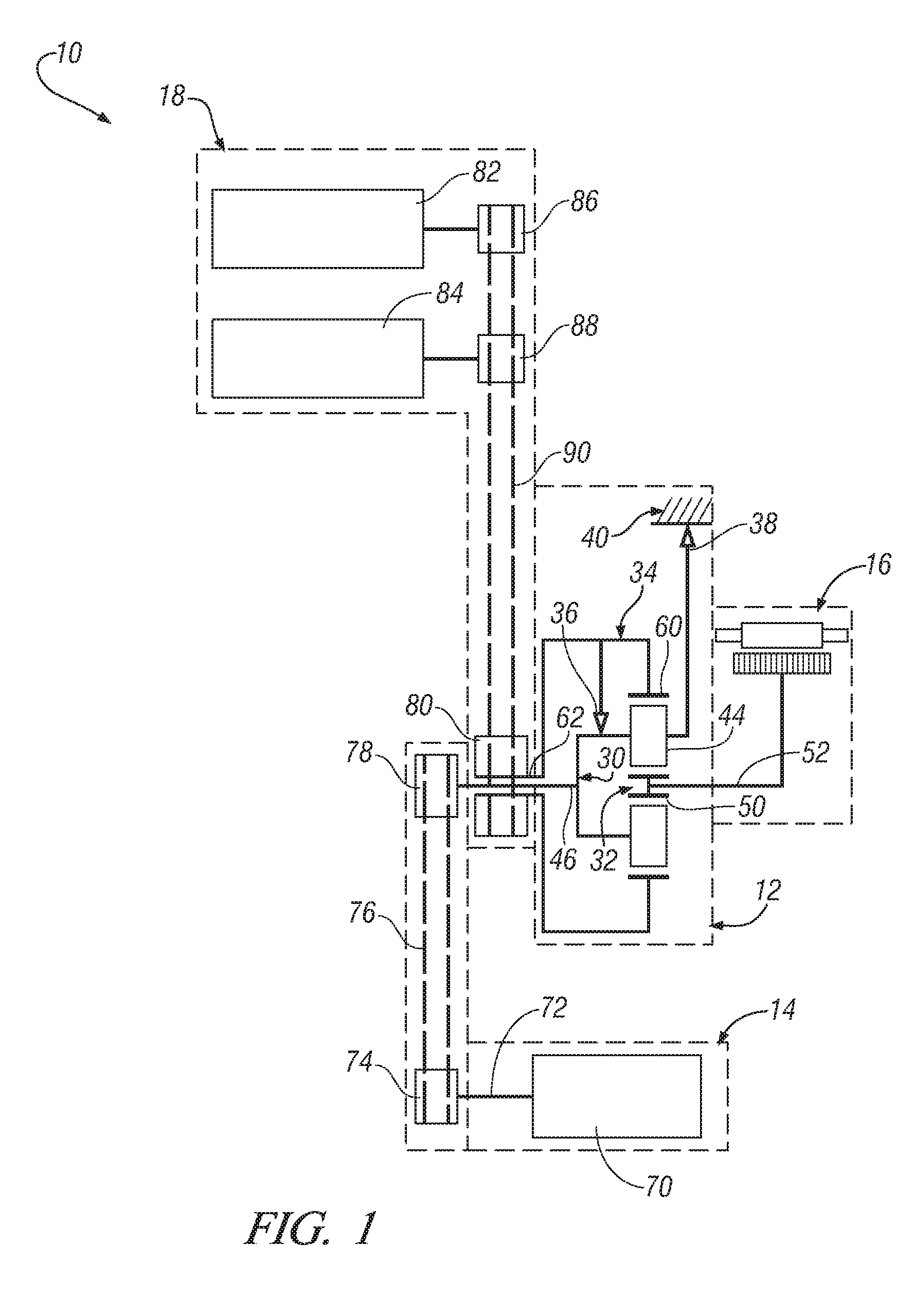
[0014]A power distribution system for a hybrid vehicle in accordance with exemplary embodiments will now be described. The power distribution system includes a power distribution apparatus. The power distribution apparatus includes an engine power transfer member, a motor / generator power transfer member, and an accessory power transfer member.

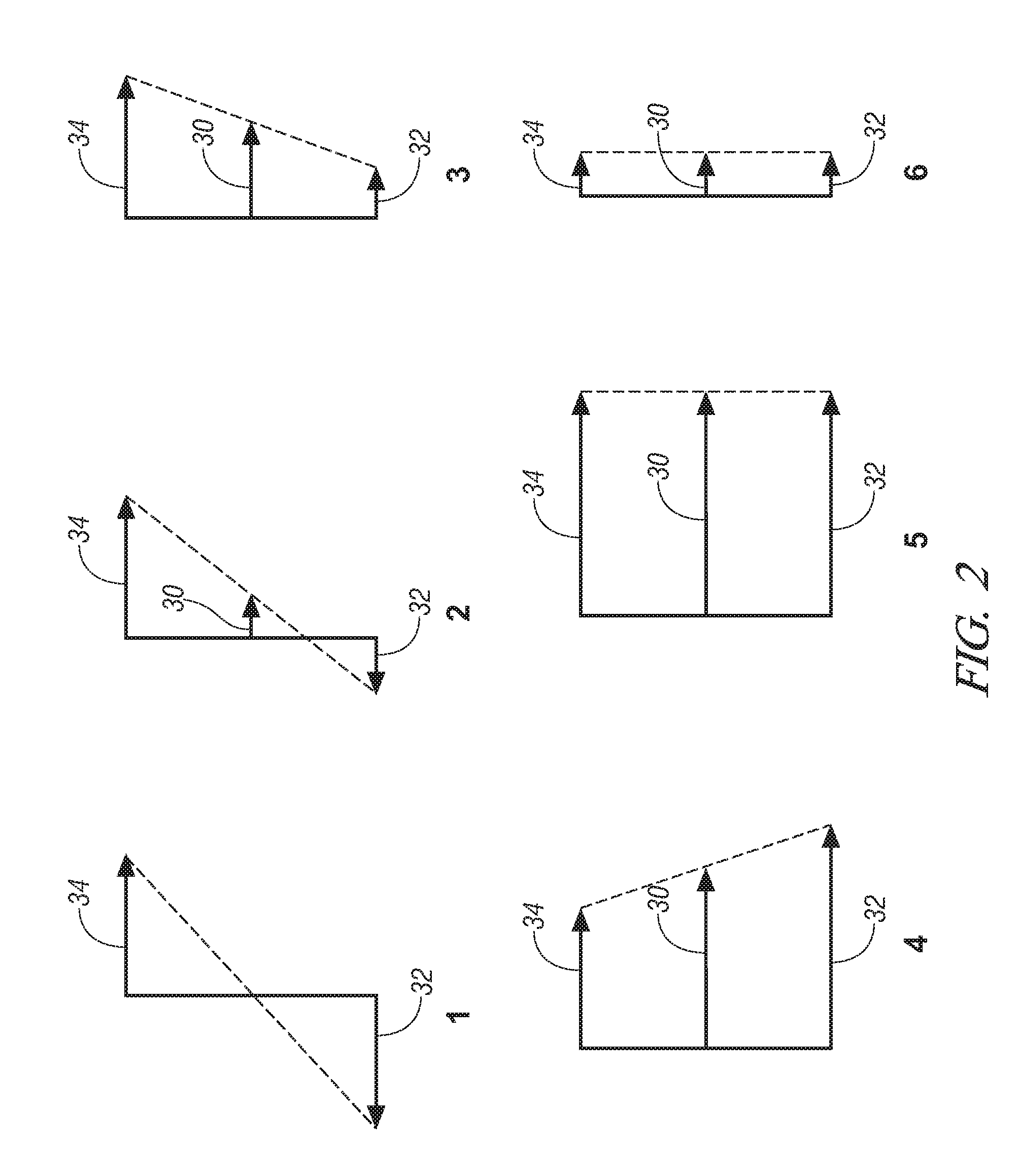
[0015]Each power transfer member is configured to communicate with the other power transfer members to transfer selected amounts of power in a vehicle during various operating conditions of the vehicle. Specifically, each power transfer member is configured to transfer rotational power. The term rotational power is meant to include any power generated by the rotational movement of a device (i.e., power comprising a torque and an angular velocity). Therefore, the power transfer member can include any member capable of transferring such power.

[0016]In an exemplary embodiment, the power transfer members will comprise shafts communicating through o...


PUM


Abstract

A power distribution system for a hybrid vehicle having an engine is disclosed. The power distribution system includes an electric motor / generator, a vehicle accessory drive system comprising a first accessory, and a power distribution apparatus. The power distribution apparatus includes a first power transfer member comprising a first shaft, the first shaft being configured to transfer power to the engine and from the engine. The power distribution apparatus further includes a second power transfer member comprising a second shaft, the second shaft being configured to transfer power to the motor / generator and from the motor / generator. The power distribution apparatus further includes a third power transfer member comprising a third shaft, the third shaft being configured to transfer power to the accessory drive system to drive the first accessory. The power distribution apparatus further includes a first clutch and a second clutch.

Description

TECHNICAL FIELD[0001]The present disclosure relates to a vehicle power distribution system and more particularly to a vehicle power distribution system for transferring power among an engine, a motor / generator, and an accessory drive system.BACKGROUND OF THE INVENTION[0002]Current vehicles utilize accessory drive systems to supply power to vehicle accessories (e.g., air conditioner systems, power steering systems, power braking, alternators, and pumps (e.g., oil, coolant and the like). The accessory drive system includes a belt coupled to the engine through one or more pulleys. A problem associated with current vehicles is that power is not transferred to the accessories as efficiently as desired. Current accessory drive systems deliver sufficient power to operate accessories over the entire range of the engine's operational speeds. Engines can operate at speeds from, for example, 500 RPM (revolutions per minute) to 8000 RPM, and the pulleys of the accessory drive systems operate at...

Claims


Application Information

Patent Timeline
Patent Type & Authority Patents(United States)
IPC IPC(8): B60L11/00
CPCB60W10/08B60W10/30B60K6/485B60K25/02B60W20/00F16H2200/2084Y10T477/26B60K2025/005B60K2025/024B60Y2400/427F16H2200/2005Y02T10/6226Y02T10/62B60K6/48B60W20/10
Inventor USORO, PATRICK B.
Owner GM GLOBAL TECH OPERATIONS LLC
Why Eureka
Eureka Blog
Learn More