Automotive road milling machine, in particular large milling machine

a road milling machine and motor technology, applied in the field of large machines, can solve the problems of no reason to provide a recess in the machine frame, the machine operator cannot precisely follow a predetermined corner, and the weight of the road milling machine is high,

Active Publication Date: 2010-07-13
WIRTGEN GMBH
View PDF26 Cites 18 Cited by
  • Summary
  • Abstract
  • Description
  • Claims
  • Application Information

AI Technical Summary

Benefits of technology

[0009]The invention enables an improved maneuvrability for road milling machines in which the milling drum is arranged between the crawler track units or wheels of the front and rear axles, in particular when driving on the left, when the zero side is located on the right side of the machine in relation to the direction of travel. The recess widening downwards and towards the front when seen in the direction of travel makes it possible to not only follow a tight pre-determined corner radius inwards, but to also monitor the steering angle of the front chassis axle directly and independent of the direction of travel.
[0010]The recess widening downwards and towards the front when seen in the direction of travel offers the advantage that the construction volume of the machine in front of the operator station is reduced as little as possible. This is of importance for the reason that a water tank is usually accommodated in the front superstructure, so that the tank volume will be reduced as little as possible by the recess. The wall section of the recess running obliquely downwards and marking the boundary towards the front, for instance, is aligned in such a manner that the angle of vision of the sitting or standing machine operator is still capable of monitoring the steering position of the front crawler track unit or wheel.
[0011]The wall section marking the boundary of the recess thus follows the visual path of the machine operator. In this way, it is achieved that an improved visibility is created for the machine operator on the one hand, which leads to a better maneuvrability of the road milling machine, and that the tank volume. is not needlessly reduced on the other hand.
[0012]To date, road milling machines with a milling width of more than 1000 mm have barely been capable of carrying out tighter corner radii, so that such corner radii, as they frequently occur in, for instance, roundabout installations, needed to be worked with a different specialized road milling machine. The invention now enables the maneuvrability of road milling machines with a milling width of more than 1000 mm to be improved significantly, so that no different road milling machines need to be used for specific road construction operations. The invention is of particular advantage in road milling machines with milling widths ranging between 1000 and 2200 mm, preferably 1200 mm to 1500 mm, and expands their application possibilities.
[0014]The arrangement of the seat for the machine operator in such an outer position improves the view of the area in front of the milling drum and of the support wheel or crawler track unit of the front chassis axle on the zero side. The design of the recess enables a marking line, which runs inward starting from the zero side, to be followed for a very long distance, thus enabling the road milling machine to be steered very precisely along the said marking line. The maneuvrability is additionally facilitated by the fact that the steering position of the front chassis axle can be monitored simultaneously.

Problems solved by technology

Such road milling machines have high weight and are therefore generally carried by a chassis with crawler track units.
Hence, there is no reason to provide a recess in the machine frame in large milling machines.
Large milling machines pose the problem, in particular in case of milling operations that lead inward relative to the zero side, that the machine operator cannot precisely follow a pre-determined corner line with a tight corner radius, because the same is blocked from view by the machine frame.
It is, however, difficult also to precisely follow a pre-determined corner line, irrespective of the direction it leads to, for the reason that the crawler track units are located underneath the machine frame and do not permit visual monitoring of the steering angle.

Method used


Image

  • Automotive road milling machine, in particular large milling machine
  • Automotive road milling machine, in particular large milling machine
  • Automotive road milling machine, in particular large milling machine

Examples


Embodiment Construction

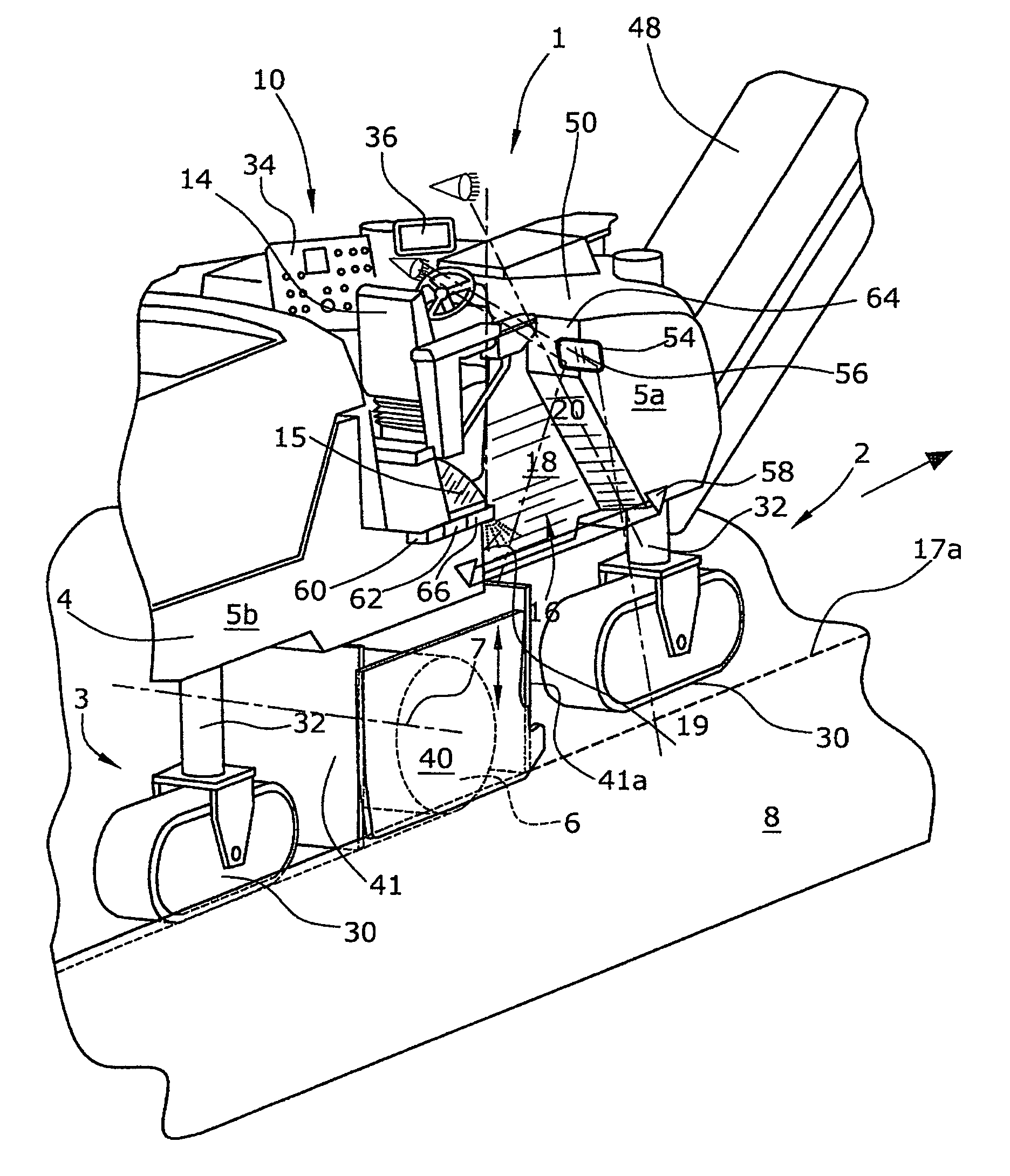
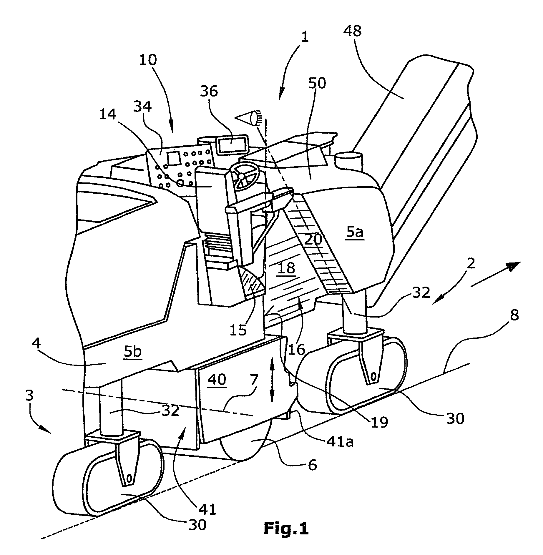
[0035]FIG. 1 shows a road milling machine 1, in particular a large milling machine with a machine frame 4 and a chassis with a steerable front axle 2, as well as with an equally steerable rear axle 3. The chassis is connected to the machine frame 4 via lifting columns 32 which enable adjustment of the distance of the machine frame 4 from a ground surface or traffic surface 8.

[0036]At the front end of the road construction machine, a transport conveyor 48 capable of slewing in both height and lateral direction is arranged for the removal of the milled material.

[0037]The front axle 2 and the rear axle 3 of the chassis may consist of two crawler track units 30 and / or two wheels each.

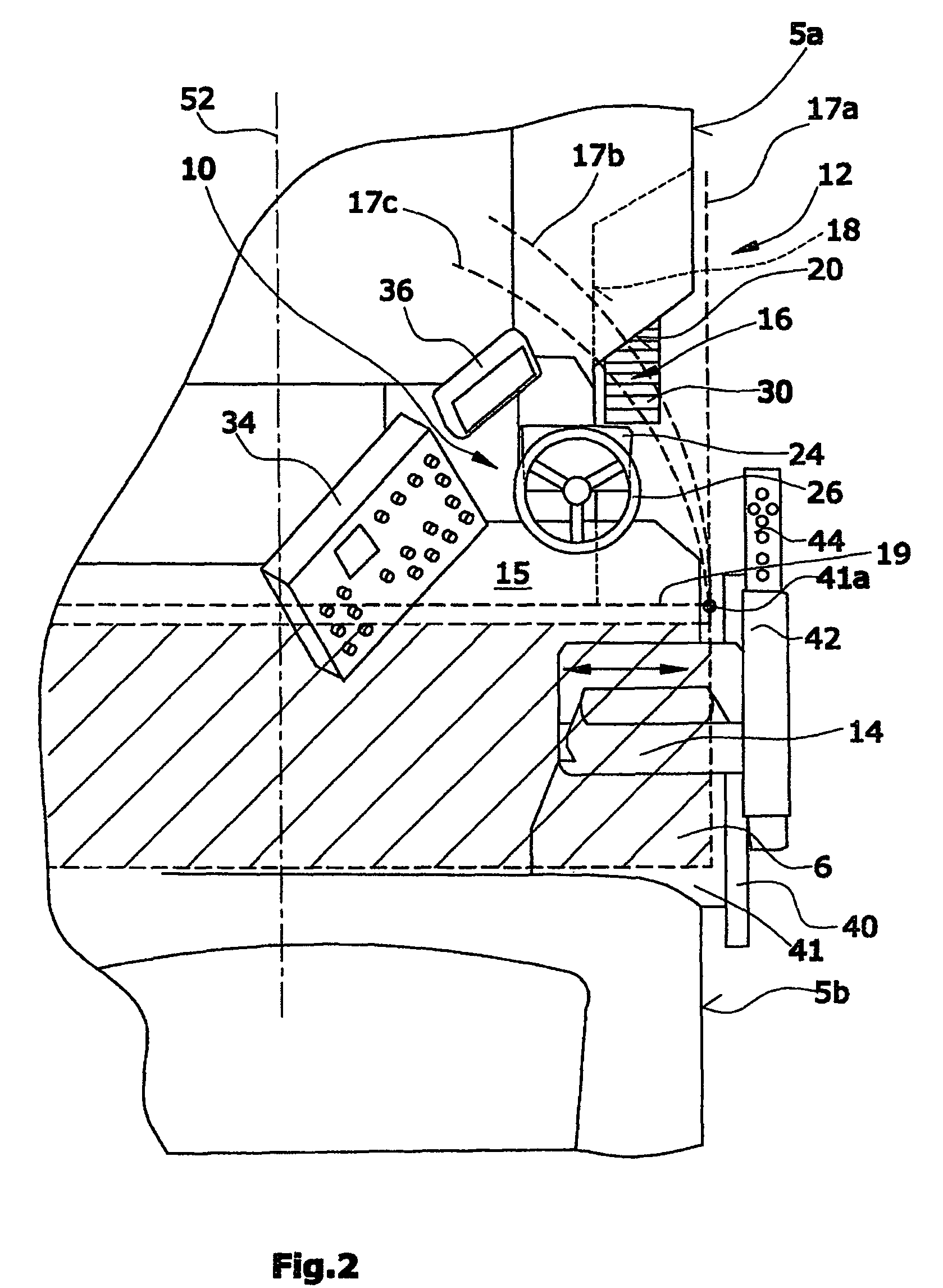
[0038]The machine frame 4 is provided with lateral outer walls 5a, 5b that run essentially vertically and parallel to the longitudinal centre-line of the road milling machine 1. It is understood that the outer walls need not run strictly vertical and absolutely parallel to the longitudinal centre-line of th...


PUM


Abstract

An automotive road milling machine, in particular large milling machine, for milling a ground surface or traffic surface, with a chassis provided with a front axle and a rear axle, consisting of crawler track units or wheels, a machine frame carried by the chassis with lateral outer walls and a longitudinal center-line, a milling drum supported at the machine frame between the crawler track units or wheels of the front axle and the rear axle, where one front end of the milling drum reaches as far as an outer side of the machine frame called the zero side for the purpose of close-to-edge milling, and an operator station with a platform for the machine operator, it is provided that the part of the machine frame located on the zero side in front of the platform of the machine operator when seen in the direction of travel is set back inwards in such a manner that a recess running in vertical direction and open towards the outer side, as well as towards the bottom and towards the top is formed in the machine frame, the said recess widening downwards and towards the front when seen in the direction of travel.

Description

BACKGROUND OF THE INVENTION[0001]The invention relates to an automotive road milling machine, in particular a large milling machine.[0002]Such road milling machines are, in principle, known already. For small milling machines, in which the milling drum is located at the level of the rear axle of the chassis and between the rear wheels, it is known to provide a recess in the lateral outer wall on the zero side of the machine that a rear support wheel or crawler track unit can swivel into.[0003]Road milling machines with a milling width of more than 1200 mm, for instance, are called large milling machines. Such road milling machines have high weight and are therefore generally carried by a chassis with crawler track units. The milling drum is mounted at the machine frame between the crawler track units of the front axle and the rear axle, and at a distance to the same.[0004]It is not customary to provide recesses in large milling machines, for large milling machines are not provided w...

Claims


Application Information

Patent Timeline
Patent Type & Authority Patents(United States)
IPC IPC(8): E01C23/16E01C23/07E21C25/00
CPCE01C19/004E01C23/088E01C2301/30
Inventor KOTTING, HEINRICHBERNING, CHRISTIANLENZ, MARTINHAHN, GUNTER
Owner WIRTGEN GMBH
Why Eureka
Try Eureka