Vertical multi-phased wind turbine system

a wind turbine and multi-phase technology, applied in the direction of machines/engines, renewable energy generation, greenhouse gas reduction, etc., can solve the problems of increasing maintenance costs, unsightly nature, and existing wind turbine designs not being as widely adapted as economically feasibl

Active Publication Date: 2010-07-13
AEROMINE TECH
View PDF15 Cites 23 Cited by
  • Summary
  • Abstract
  • Description
  • Claims
  • Application Information

AI Technical Summary

Problems solved by technology

Unfortunately, existing wind turbine designs have not been as widely adapted as is economically feasible.
There are unforeseen problems with public reaction to the unsightly nature of the turbines and their visual dominance on a landscape, especially where there may be multiple installations of air turbines, often moving at different speeds and rotations with respect to each other, which may be viewed at the same time by a casual observer.
There have been other issues.
Existing wind turbines are often high off the ground, which increases maintenance costs due to poor accessibility.
Some turbines have to reduce their operating speeds due to birds colliding with the turbine blades.
There are infrastructure problems, where high voltage transmission lines are unavailable in favorable wind areas.
However, the practicality of the design is highly questionable.
The practical aspects of the design are highly limited.
The venturi design does not consider appropriate methods to re-entrain the turbine exhaust air back into the prevailing wind in an efficient manner, and the design is overly complicated.
Also, the efficiency of the wind ‘catch’ and wind ‘discharge’ has not been carefully planned.
Further, the building is a fixed size, and it is difficult to optimize the whole design when the wind ‘catch’ area is a constant size.
It is less appealing to have the air intake close to the ground as the wind speed is lower.
However, the design of the air stream through the central opening of the framework and the closed baffles is inadequate.
As stated previously, a relatively large volume of air is needed to create the vacuum needed to draw a significant amount of air vertically, and the effect is not as efficient as other methods.
This design is not configured to catch a prevailing wind from any direction, and the simple structure is likely to be damaged in a high wind.
The overly large design is meant to catch the movement of air from a thermal effect when the air is heated by the sun.
Again, in both of these patents no thought is given to providing a large exit space just after the turbine blades where the prevailing wind is allowed to enter and additionally generate power by rotating the turbine blades.
None of these patents provides a large exit space just after the turbine blades where the prevailing wind is allowed to enter and additionally generate power by rotating the turbine blades.

Method used


Image

  • Vertical multi-phased wind turbine system
  • Vertical multi-phased wind turbine system
  • Vertical multi-phased wind turbine system

Examples


Embodiment Construction

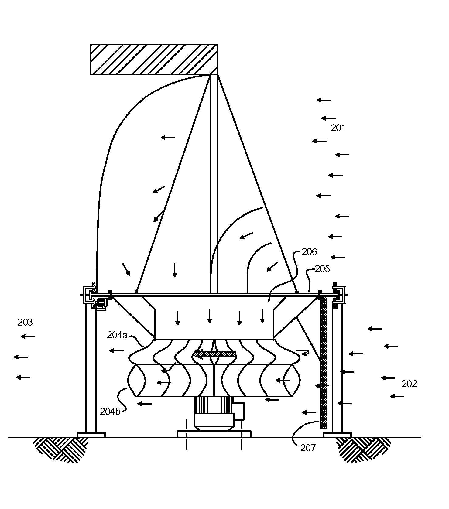
[0029]The present invention is a system designed to produce electricity at cost effective rates in an environmentally friendly manner at power outputs of approximately 0.10 to 50 kW. It is especially useful in areas where the wind velocity and turbulence increases in places that occur around small hills and tall buildings. It may be employed successfully in the heavily populated downtown sections of major cities. Multiple units can be utilized and may be sized for any given location as the opportunity may arise. Generally speaking, areas with average wind speeds of at least 12 mph are considered to be the most favorable locations for wind power.

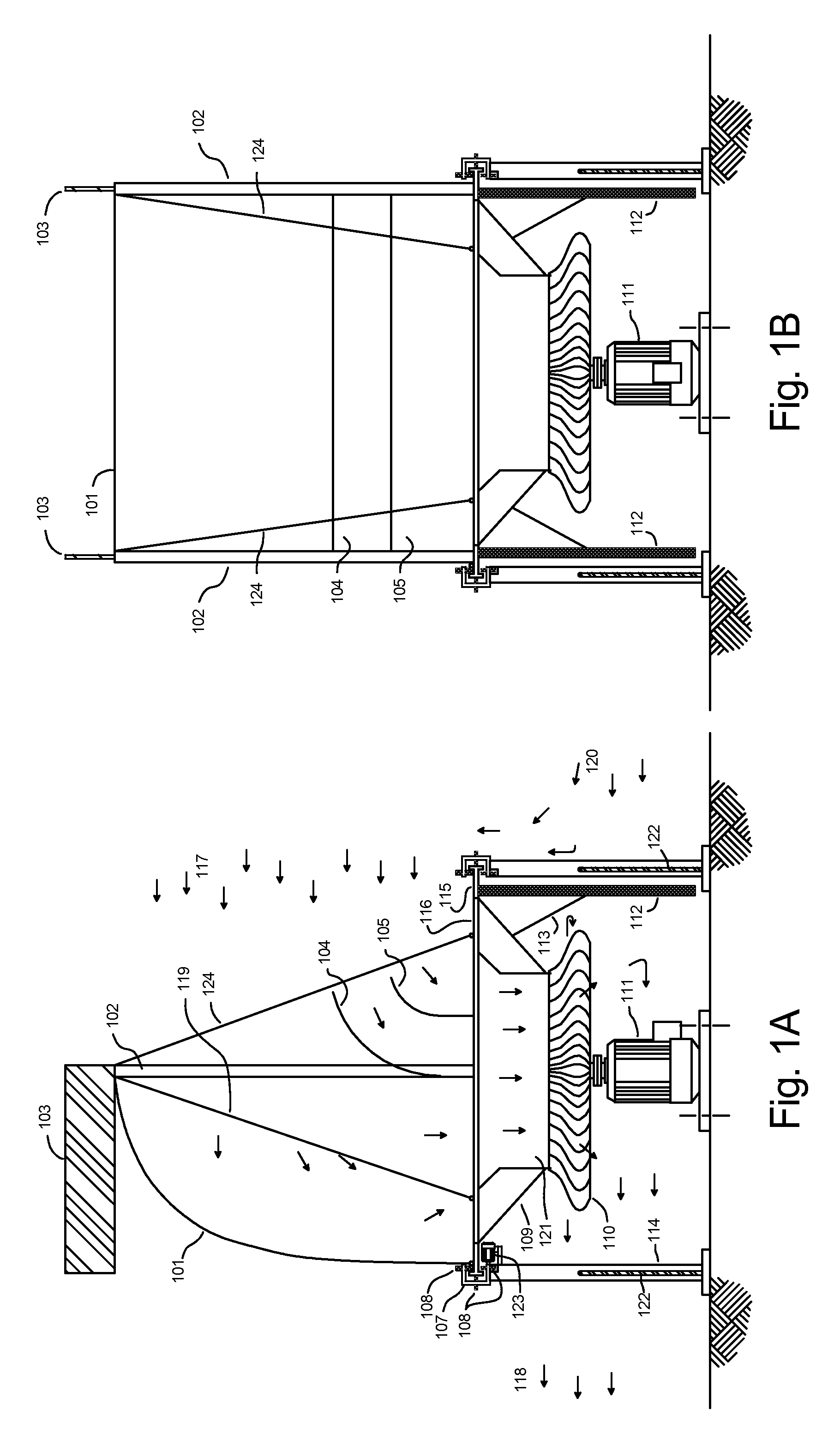
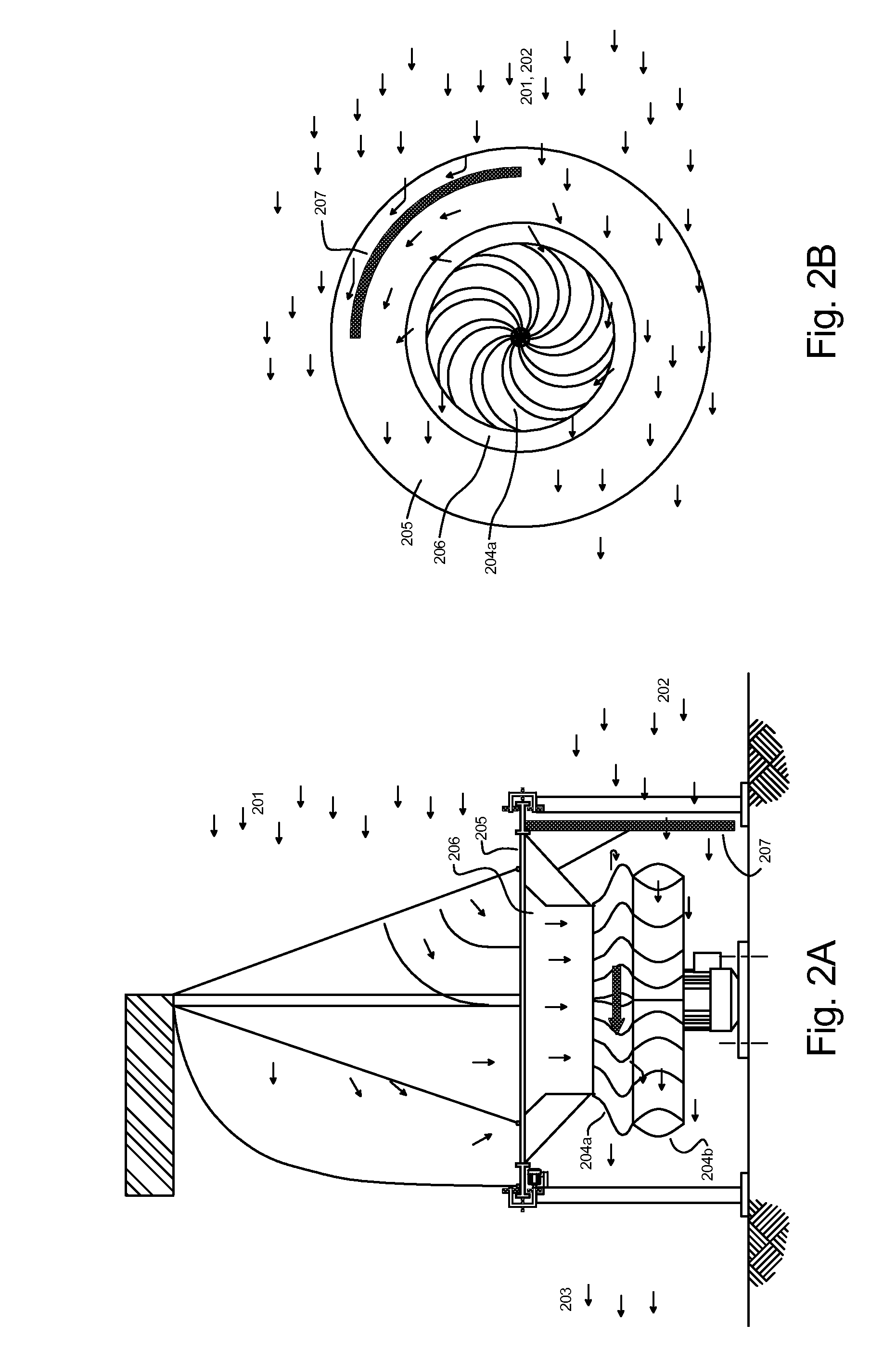
[0030]FIGS. 1A-1B show two cross sectional views of a preferred embodiment, general arrangement of the invention. A large air scoop 101 made from a flexible material, such as used in the sailing industry, is hoisted above a vertical axis power generating turbine 110, 111 in order to utilize the upper prevailing wind 117 and direct the maximum...


PUM


Abstract

A vertical axis multi-phased wind turbine power generating system is disclosed. An adjustable air scoop directs air from a first phase of the prevailing wind into an air turbine for efficient power generation. An exit section, which uses a second phase of the prevailing wind in combination with an optional and adjustable exit section drag curtain or barrier, provides for efficient re-entrainment of this first stage of power generating air back into the downstream prevailing wind. The adjustable air scoop and adjustable exit drag curtain or barrier, where utilized, is automatically rotated in a self correcting manner to be suitably and optimally oriented to the prevailing wind direction. The design provides for a second stage of power generation to be accomplished by additionally utilizing a portion of the second phase of prevailing wind to directly or indirectly drive the turbine in a second stage of power production.

Description

CROSS REFERENCE TO RELATED APPLICATIONS[0001]This application is a continuation in part of U.S. application Ser. No. 11 / 608,658 filed on Dec. 8, 2006 now U.S. Pat. No. 7,488,150 which claims the benefit of U.S. Provisional Application No. 60 / 766,003 filed on Dec. 29, 2005. Both the provisional application and the prior non-provisional utility application are incorporated by reference herein.STATEMENT REGARDING FEDERALLY SPONSORED RESEARCH OR DEVELOPMENT[0002]Not applicable.REFERENCE TO SEQUENCE LISTING, A TABLE, OR COMPUTER PROGRAM LISTING[0003]Not applicable.BACKGROUND OF THE INVENTION[0004](1) Field of the Invention[0005]This invention is directed toward wind driven power generating systems, in particular, wind driven power generating systems useful for the production of power, such as electricity. The present invention comprises an adjustable air scoop inlet section, an air turbine section of unique design, and an adjustable outlet section, which may include an adjustable drag cu...

Claims


Application Information

Patent Timeline
Patent Type & Authority Patents(United States)
IPC IPC(8): F03D3/04
CPCF03D1/04F03D3/0481F05B2240/13F05B2250/5012Y02B10/30Y02E10/72Y02E10/74Y10S415/907Y02E10/728F03D9/35F03D3/049F03D3/0454
Inventor KRIPPENE, BRETT C.
Owner AEROMINE TECH
Why Eureka
Try Eureka