
Floating marine debris trap

a technology of floating marine debris and traps, which is applied in the direction of water cleaning, swimming pools, separation processes, etc., can solve the problems of suspicious negative effects on worldwide marine resources, certain classes of marine trash, and negative effects on both pelagic and local marine wild li

Inactive Publication Date: 2011-08-18
GRIFFITH THEODORE +2
View PDF10 Cites 2 Cited by
  • Summary
  • Abstract
  • Description
  • Claims
  • Application Information

AI Technical Summary

Benefits of technology

The invention is a system for containing water-borne debris that can be removed to sanctioned disposal facilities. It consists of a door frame / door assembly, called DFD, which is installed between oil slick containment boom. The DFD assembly and different boom deployment configurations create a collection / containment system that can be used in various water conditions and marine structures. The system can be used to collect debris from boats or structures and dispose of it in local sanctioned facilities. The preferred embodiment of the system involves placing existing oil slick boom arrays or new DFD / boom arrays in areas where there is natural tidal, current, or wind action flow.

Problems solved by technology

Known as the “Pacific Gyre” or “Great Pacific Garbage Patch”; It is said that each ocean has a gyre and another debris vortex may be forming in the Atlantic Ocean.1 Scientific studies of the debris field located in the Eastern Pacific Ocean have determined that certain classes of marine trash have negative effects on both pelagic and local marine wild life.2 While states and countries enact laws to promote conservation of marine resources, the proliferation of ocean and waterway debris is causing unknown but suspicious negative effects on worldwide marine resources.

Method used


Image

  • Floating marine debris trap
  • Floating marine debris trap
  • Floating marine debris trap

Examples


Embodiment Construction

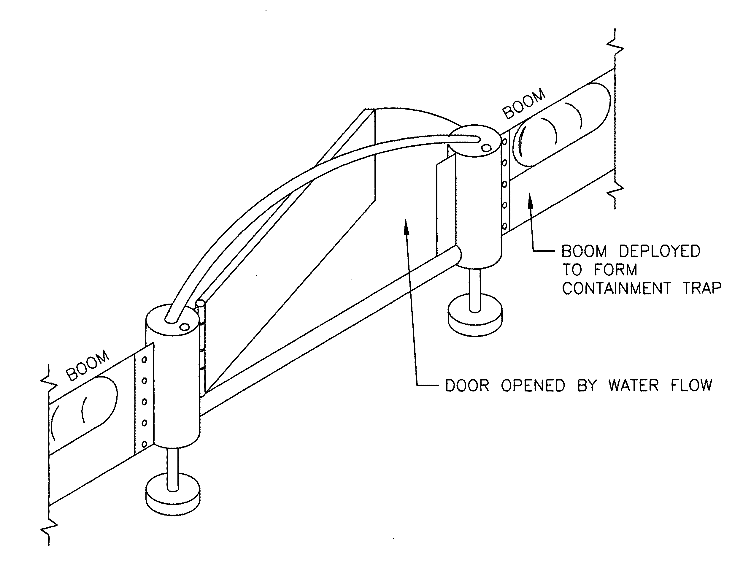
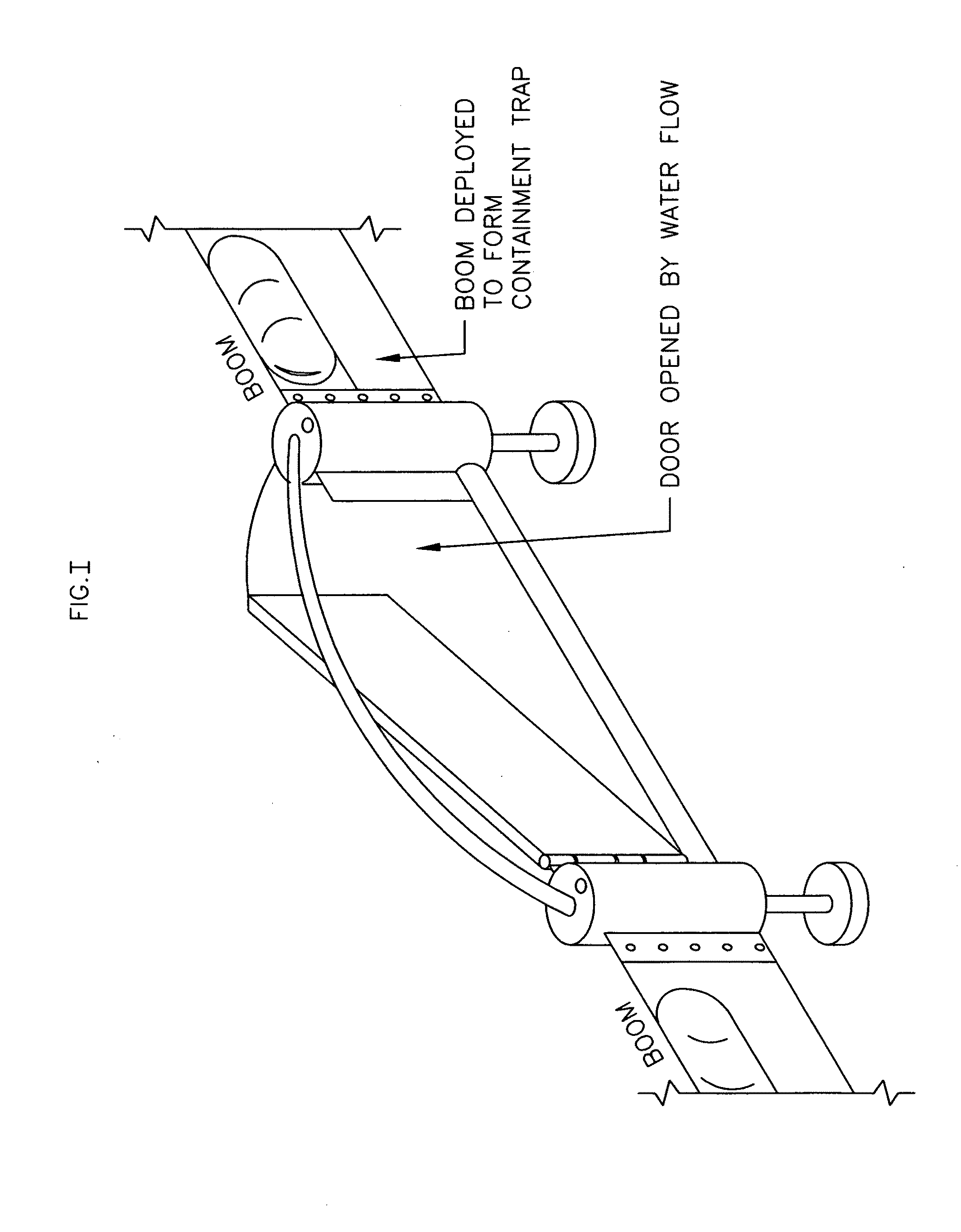
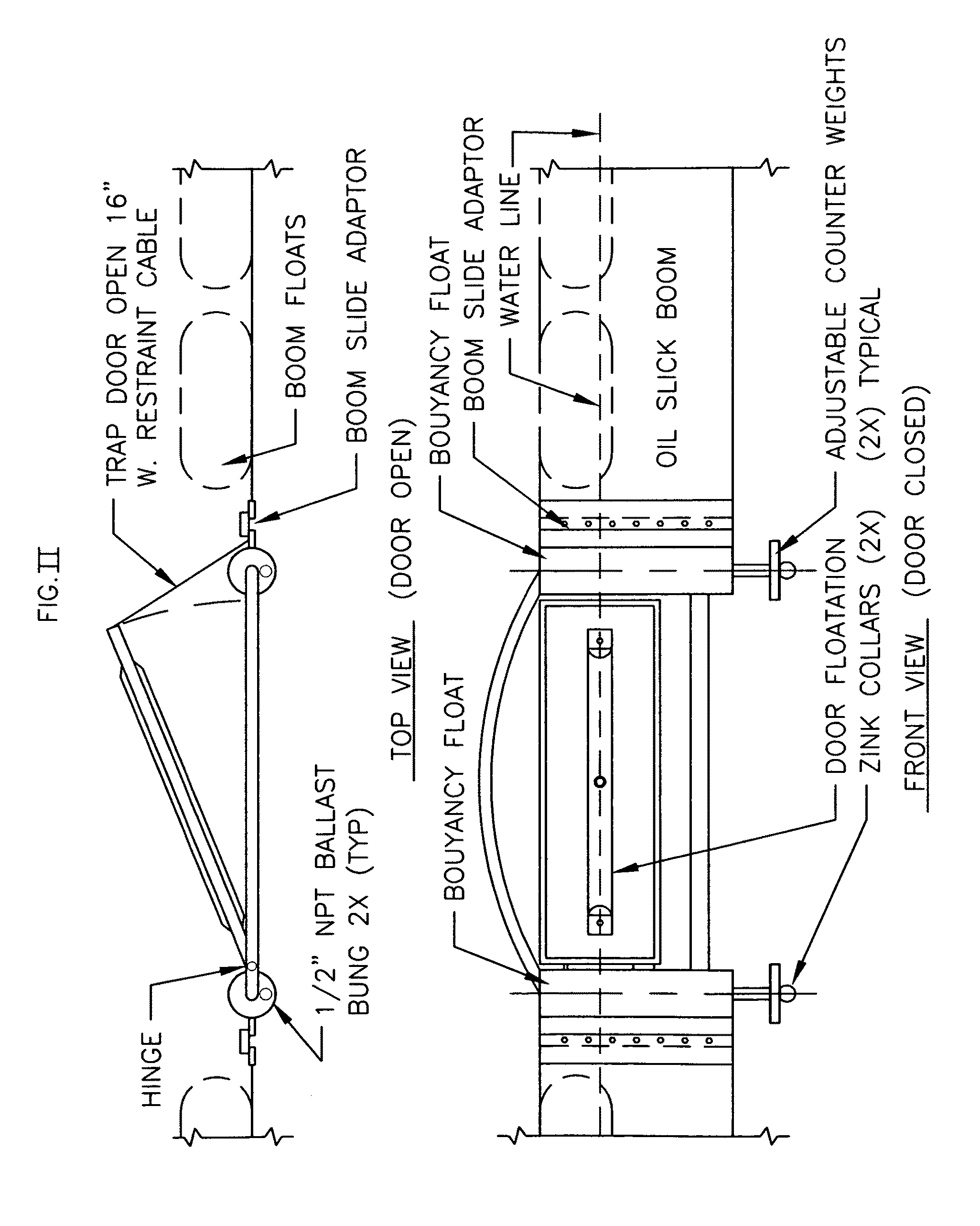
[0016]The floating marine debris trap is a combination of a door frame / door assembly connected to commercial oil slick containment boom. The invention is a combination of a unique floating door frame / door assembly and a series of oil slick boom deployment methods that form the floating marine debris trap. Regularly available commercial oil slick containment boom combined with various types of door frame / door entry systems and specific deployment methods will trap both oil based water contaminants and floating debris. Trapped aquatic debris may be returned to the water or disposed or per local, state and federal regulations. Four different door configurations are cited as examples of adapting the debris trap opening to the correct conditions of tidal flow, current, and (or) wind action. The diagrams #1-#4 depict the standard door frame and the different door configurations. Utilizing the various deployment methods, floating marine debris may be contained and collected for commercial ...


PUM

PropertyMeasurementUnit
lengthsaaaaaaaaaa
specific areaaaaaaaaaaa
flexibilityaaaaaaaaaa

Abstract

A system for capturing and containing waterborne floating debris in bays, harbors, rivers, and other waterways with current, tidal, or wind action flow. This system utilizes a hinged capture gate attached to any of the commercially produced oil slick containment boom systems along with an anchoring deployment that orients the debris trap perpendicular to current, prevailing wind, and tidal flow in employed waterways. The door frame / door gate invention along with the alignment and anchoring of the boom material will allow floating debris to be captured and held within the boom material for later collection and disposal or recycle. This system allows mandated oil slick boom to serve the extended purpose of collecting floating debris before it enters the open oceans and inland waterways. Thousands of yards of oil slick boom are in place that could be utilized to catch and contain waterborne trash and valuable recyclables in every coastal bay, harbor, and waterway worldwide. Removal of floating debris from the debris trap is accomplished with a small boat or skiff and a dip net. This trash may be collected for disposal by municipal agencies that both recycle, remove and (or) compost land borne waste.

Description

BACKGROUND OF THE INVENTION[0001]The recent discovery of a major Pacific Ocean current break containing one thousand square miles of floating debris and the inundation of beaches with trash in the Hawaiian Island chain delineates the need to capture, contain, and remove waterborne debris that originates from land sources. Known as the “Pacific Gyre” or “Great Pacific Garbage Patch”; It is said that each ocean has a gyre and another debris vortex may be forming in the Atlantic Ocean.1 Scientific studies of the debris field located in the Eastern Pacific Ocean have determined that certain classes of marine trash have negative effects on both pelagic and local marine wild life.2 While states and countries enact laws to promote conservation of marine resources, the proliferation of ocean and waterway debris is causing unknown but suspicious negative effects on worldwide marine resources. The obvious solution to the vast trash pile in our ocean and resultant water pollution is to collect...

Claims


Application Information

Patent Timeline
Patent Type & Authority Applications(United States)
IPC IPC(8): C02F1/40B01D17/12
CPCB01D17/0211C02F1/40C02F2103/007E02B15/0835E02B15/0807E02B15/0814E02B15/08Y02A20/204
Inventor GRIFFITH, THEODOREHEBERT, II, RICHARD JOSEPHTAYLOR, ROGER DEAN
Owner GRIFFITH THEODORE
Learn More