Umbilical

a technology of umbilical and splint, which is applied in the field of umbilical, can solve the problems of not solving the problem in considerable extent, and the depth to which the traditional construction umbilical can be used is limited

Active Publication Date: 2010-07-13
AKER SOLUTIONS AS
View PDF13 Cites 42 Cited by
  • Summary
  • Abstract
  • Description
  • Claims
  • Application Information

AI Technical Summary

Problems solved by technology

Thus the sea depth to which the umbilical having the traditional construction can be used is limited.
This, however, do not solve the problem in considerable extent.

Method used


Image

  • Umbilical
  • Umbilical
  • Umbilical

Examples


Embodiment Construction

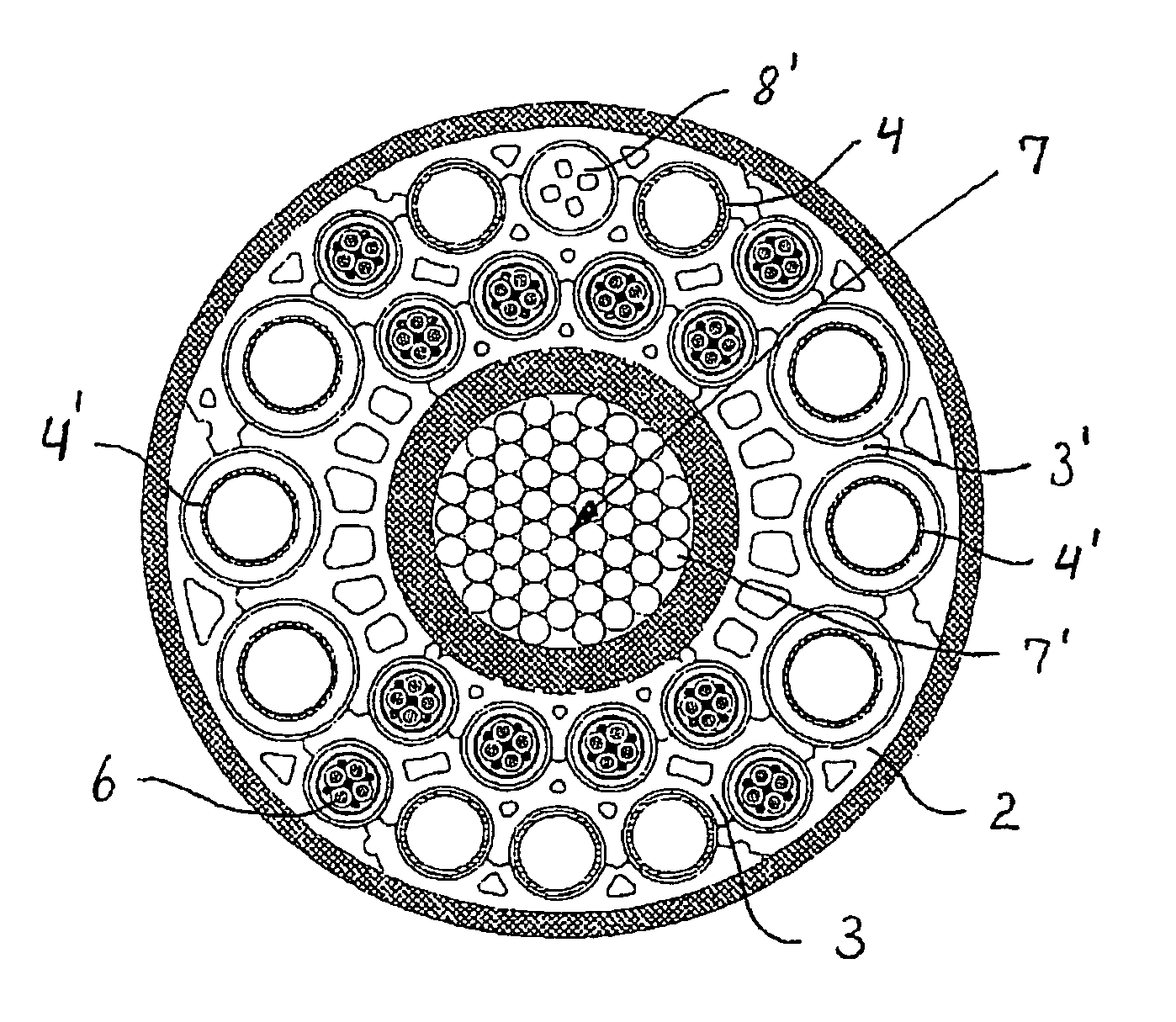
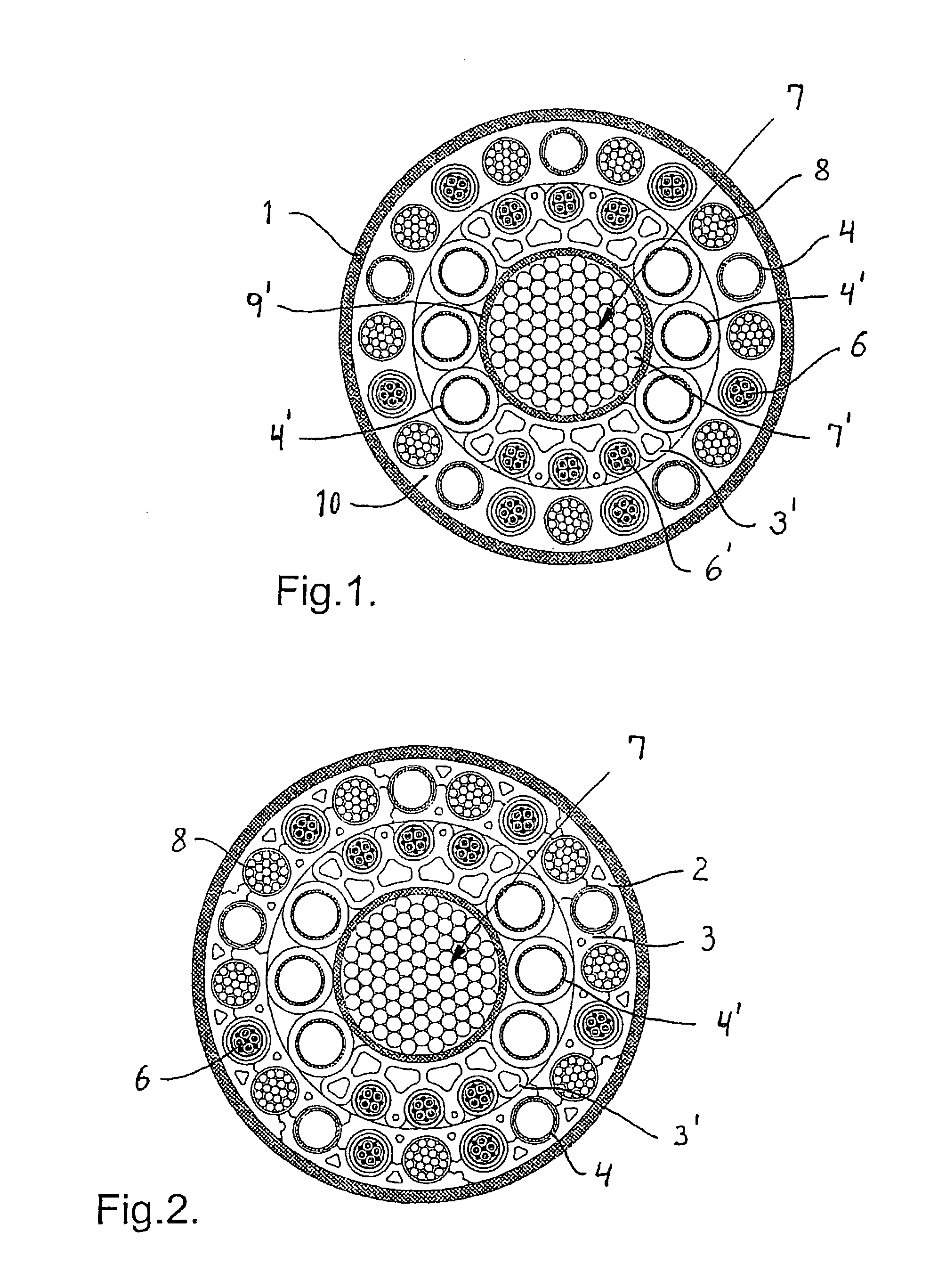
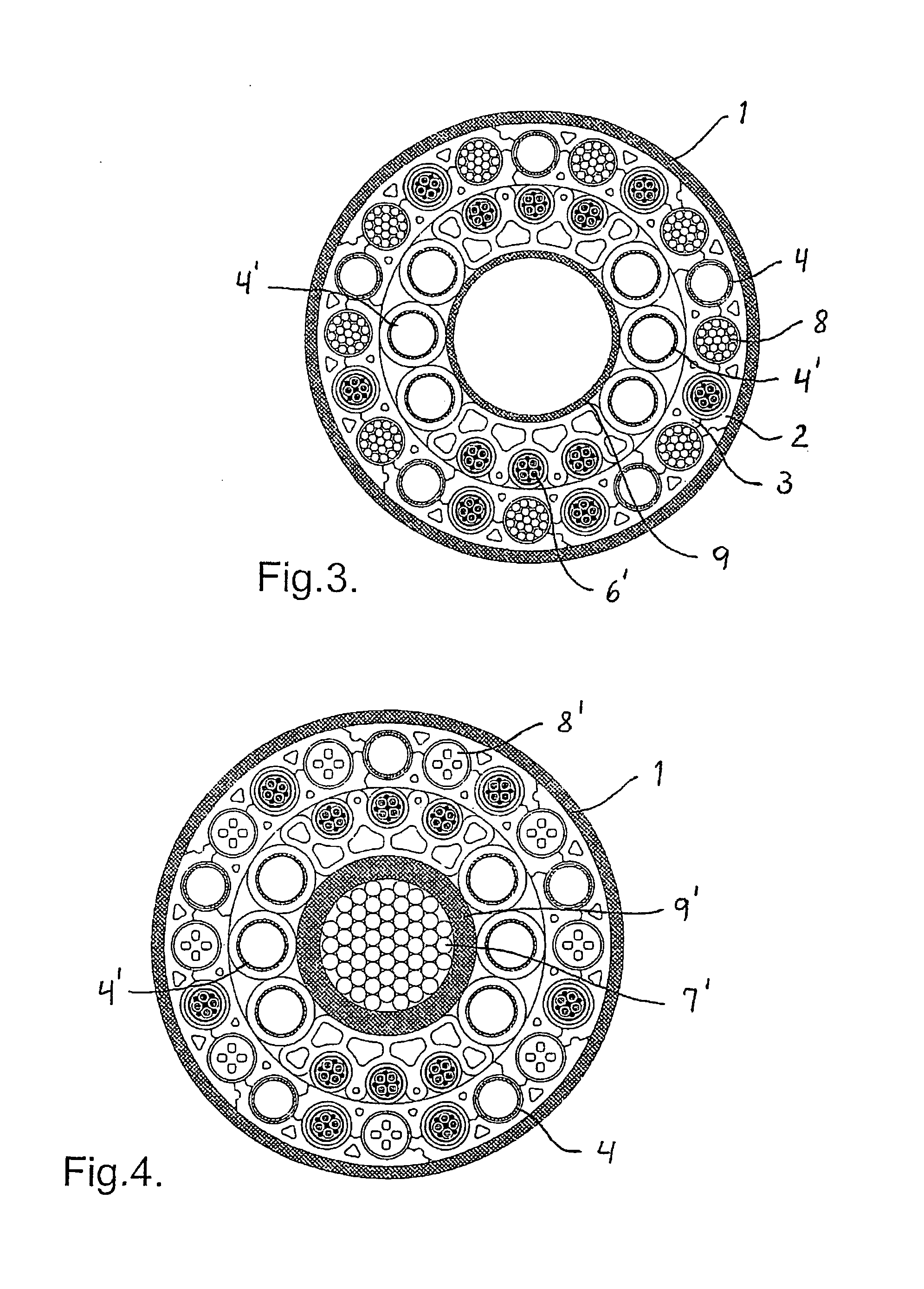
[0028]It is to be understood that it is possible with two variants of the transversal cross section of the umbilicals shown in FIG. 1-9, which do not appear from the figures, namely one where the individual elements of the umbilical are lying with a certain laying length about the longitudinal axis of the umbilical, and one variant where the individual elements are lying more or less in a straight line substantially parallel to the longitudinal axis of the umbilical. For the detailed construction of a traditional umbilical and how it can be manufactured reference is given to the previously mentioned publication WO 93 / 17176.

[0029]The umbilical according to FIG. 1 is basically constructed of the following elements: load carrying element 7 consisting of a bundle of rods 7′ of composite material, inner channel elements 3′, for example of polyvinylchloride (PVC), electric conductors / wires 6, 6′, fluid pipes 4, 4′ normally made of steel, weight elements 8, or further strength elements 8, ...


PUM

PropertyMeasurementUnit
sea depthsaaaaaaaaaa
transmissionaaaaaaaaaa
electric currentaaaaaaaaaa

Abstract

An umbilical for transfer of fluids and electric current / signals between the sea surface and equipment deployed on the sea bed, in particular in deep waters, is disclosed. The umbilical comprises a number of pipes (4, 4′) and electric conductors / wires (6, 6′) collected in a bundle, a filler material (10, 2, 3, 3′) lying at least partly around and between the pipes (4, 4′) and the conductors / wires (6, 6′), and a protective sheath (1) enclosing the pipes, conductors / wires and filler material. The load carrying elements (7) of the umbilical are light weighted rods (7′) of composite material that can either be collected in bundles or appear individually or in a combination thereof.

Description

BACKGROUND OF THE INVENTION[0001]The present invention relates to an umbilical for transmission of fluids and electric current / signals between the sea surface and equipment located on the sea bed, in particular in deep waters, comprising a number of pipes and electric conductors / wires collected in a bundle, a filler material arranged at least partly around and between the pipes and conductors / wires, and a protective sheath enclosing the pipes, conductors / wires and filler material.[0002]Umbilicals of this type are constructed as a composed structure which is able to transfer hydraulic liquids, chemicals, fluids, electric and optical signals and electric power between equipment on the sea bed and on the sea surface. An early version of such umbilicals is known from WO 93 / 17176. Typical for this umbilical is that most of the load transfer takes place in a centrally located steel pipe of substantial dimension. Further examples of prior art are disclosed in GB 2 326 177 A and GB 2 326 75...

Claims


Application Information

Patent Timeline
Patent Type & Authority Patents(United States)
IPC IPC(8): H01B7/00E21B17/01F16L9/19F16L11/127F16L11/22H01B7/14
CPCF16L11/127F16L11/22H01B7/045
Inventor FIGENSCHOU, ARILD
Owner AKER SOLUTIONS AS
Why Eureka
Try Eureka