Method and apparatus to facilitate cooling turbine engines

a technology of gas turbine engines and transition pieces, which is applied in the direction of mechanical equipment, machines/engines, stators, etc., can solve the problems of reducing the efficiency of cooling the transition pieces, and achieve the effect of facilitating inducing turbulence and facilitating assembly of gas turbine engines

Inactive Publication Date: 2010-07-20
GENERAL ELECTRIC CO
View PDF11 Cites 12 Cited by
  • Summary
  • Abstract
  • Description
  • Claims
  • Application Information

AI Technical Summary

Benefits of technology

[0004]In one aspect, a method facilitates assembling a gas turbine engine including a combustor assembly and a nozzle assembly. The method comprises providing a transition piece including a first end, a second end, and a body extending therebetween, where the body includes an inner surface, an opposite outer surface, coupling the first end of the transition piece to the combustor assembly, and coupling the second end of the transition piece to the nozzle assembly such that a turbulator extending helically over the outer surface of the transition piece extends from the transition piece first end to the transition piece second end to facilitate inducing turbulence to cooling air supplied to the combustor assembly.

Problems solved by technology

However, as the number of turbulators is decreased, the efficiency of cooling the transition piece may also be decreased.

Method used


Image

  • Method and apparatus to facilitate cooling turbine engines
  • Method and apparatus to facilitate cooling turbine engines
  • Method and apparatus to facilitate cooling turbine engines

Examples


Embodiment Construction

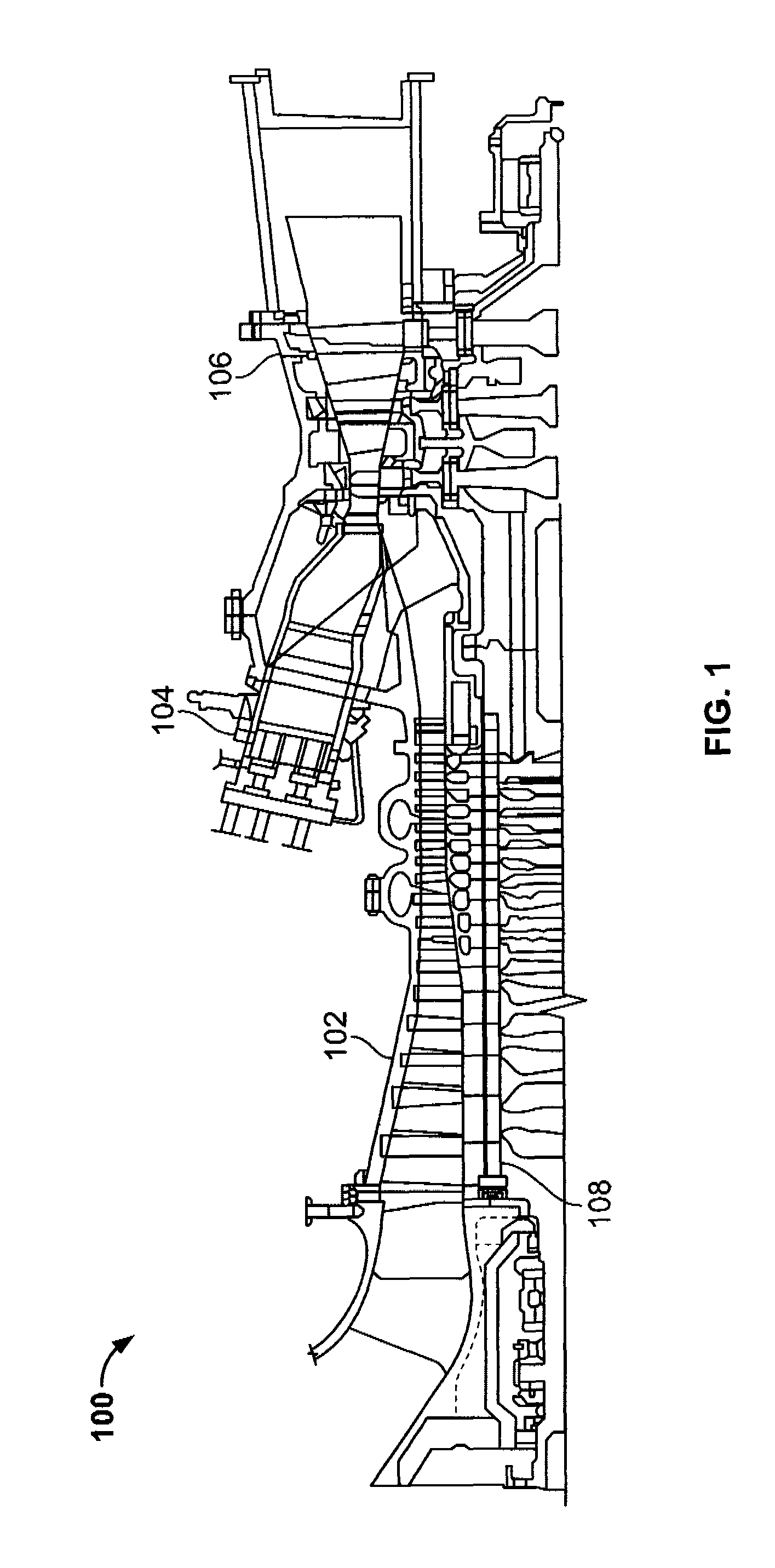
[0010]FIG. 1 is a schematic cross-sectional view of an exemplary gas turbine engine 100. Engine 100 includes a compressor assembly 102, a combustor assembly 104, a turbine assembly 106 and a common compressor / turbine rotor shaft 108. It should be noted that engine 100 is exemplary only, and that the present invention is not limited to engine 100 and may instead be implemented within any gas turbine engine that functions as described herein.

[0011]In operation, air flows through compressor assembly 102 and compressed air is discharged to combustor assembly 104. Combustor assembly 104 injects fuel, for example, natural gas and / or fuel oil, into the air flow, ignites the fuel-air mixture to expand the fuel-air mixture through combustion and generates a high temperature combustion gas stream (not shown). Combustor assembly 104 is in flow communication with turbine assembly 106, and discharges the high temperature expanded gas stream into turbine assembly 106. The high temperature expande...


PUM


Abstract

A method facilitates assembling a gas turbine engine including a combustor assembly and a nozzle assembly. The method comprises providing a transition piece including a first end, a second end, and a body extending therebetween, where the body includes an inner surface, an opposite outer surface, coupling the first end of the transition piece to the combustor assembly, and coupling the second end of the transition piece to the nozzle assembly such that a turbulator extending helically over the outer surface of the transition piece extends from the transition piece first end to the transition piece second end to facilitate inducing turbulence to cooling air supplied to the combustor assembly.

Description

BACKGROUND OF THE INVENTION[0001]This invention relates generally to gas turbine engines and more particularly, to transition pieces used with gas turbine engines.[0002]At least some known gas turbine engines include a transition piece that is coupled between a combustor assembly and a turbine nozzle assembly. To facilitate controlling operating temperatures of the transition piece within known engines, cooling air is channeled from a compressor towards the transition piece. More specifically, in at least some known gas turbine engines, the cooling air is discharged from the compressor into a plenum that extends at least partially around the transition piece of the combustor assembly. A portion of the cooling air entering the plenum is supplied into a channel defined between an impingement sleeve extending around the transition piece and the transition piece. Cooling air entering the cooling channel is discharged towards a combustor.[0003]To enhance the effectiveness of the cooling ...

Claims


Application Information

Patent Timeline
Patent Type & Authority Patents(United States)
IPC IPC(8): F02C1/00F02G3/00
CPCF01D9/023F05D2260/2212F02C7/12F02C7/18F01D25/12
Inventor INTILE, JOHN CHARLESPOYYAPAKKAM, MADHAVANRAO, GANESH PEJAWARKALEESWARAN, KARTHICK
Owner GENERAL ELECTRIC CO
Why Eureka
Try Eureka