Turbine engine annular combustion chamber with alternate fixings

a technology for turbine engines and combustion chambers, which is applied in the direction of machines/engines, mechanical equipment, lighting and heating apparatus, etc., can solve the problems of loss of clamping transiting between the flanges, cracks in the region of the bolt connection on the cowling and/or the chamber bottom, and the type of combustion chamber architecture poses many problems, and achieves sufficient flexibility and easy assembly.

Active Publication Date: 2010-07-20
SN DETUDE & DE CONSTR DE MOTEURS DAVIATION S N E C M A
View PDF22 Cites 17 Cited by
  • Summary
  • Abstract
  • Description
  • Claims
  • Application Information

AI Technical Summary

Benefits of technology

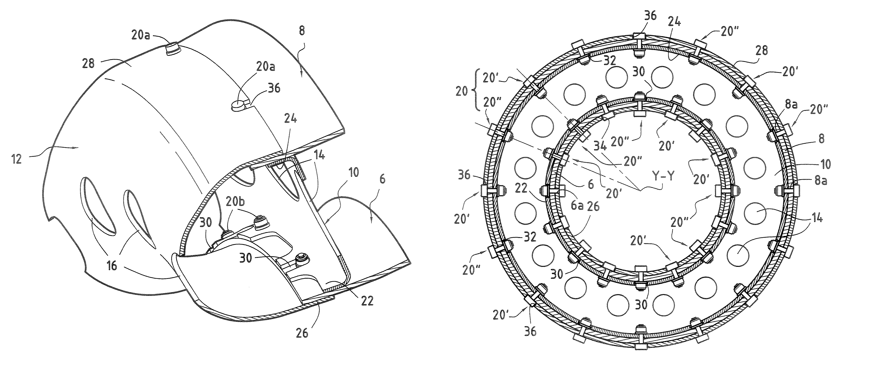
[0006]The main aim of the present invention is therefore to overcome such drawbacks by proposing an annular combustion chamber architecture that is easy to assemble and has sufficient flexibility to avoid the formation of cracks whilst retaining a necessary clamping effectiveness.
[0008]Alternating the fixing of the longitudinal walls on the chamber bottom and the cowling of the combustion chamber makes it possible to reduce the stacking up of manufacturing tolerances of these elements by a third. This results in less rigidity of the assembly and thus better closing up between these elements during assembling of the chamber and reduction of the risks of formation of cracks.
[0011]According to another advantageous provision of the invention, the first fixings between the inner longitudinal wall and the chamber bottom are situated opposite the second fixings between the outer longitudinal wall and the cowling, and the second fixings between the inner longitudinal wall and the cowling are situated opposite the first fixings between the outer longitudinal wall and the chamber bottom. This provision makes it possible to avoid any cyclic dissymmetry of the azimuthal flexibilities and rigidities and therefore prevent any damaging effect that may be generated by the vibratory stresses of the combustion chamber during its operation.
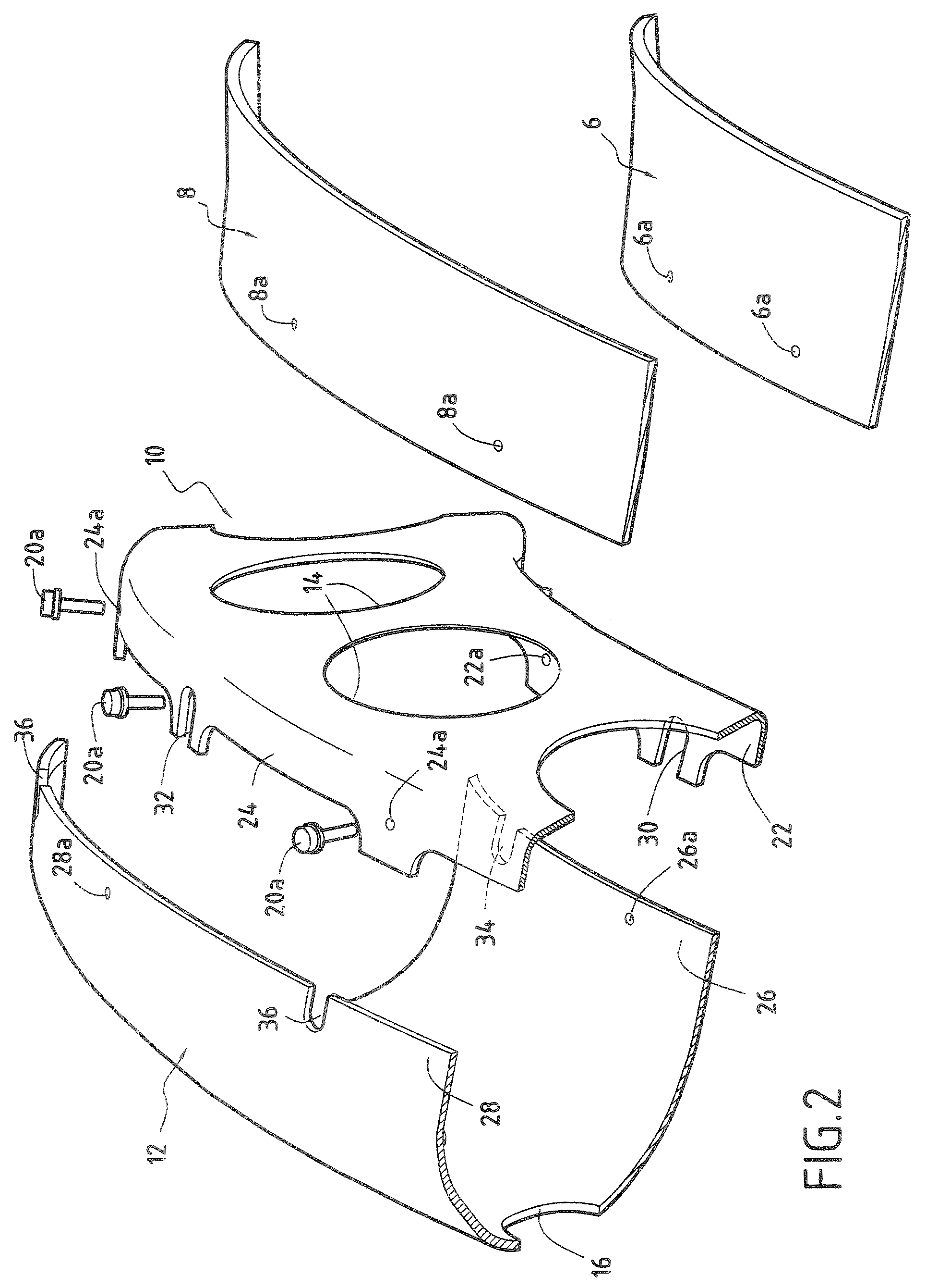
[0012]The flanges of the chamber bottom preferably comprise notches made in the region of the second fixings between the longitudinal walls and the cowling. Similarly, the flanges of the cowling advantageously comprise notches made in the region of the first fixings between the longitudinal walls and the chamber bottom. The presence of notches thus makes it possible to facilitate the assembling of the combustion chamber.

Problems solved by technology

In practice, this type of combustion chamber architecture poses many problems.
In particular, the different elements of the combustion chamber have large manufacturing tolerances, which leads to stacking up of the tolerances resulting in poor closing up between these elements when the combustion chamber is being assembled, which creates a loss as regards the clamping transiting between the flanges.
Therefore, during operation, the vibrations caused by the combustion of gases inside the combustion chamber lead to the formation of cracks in the region of the bolt connections on the cowling and / or the chamber bottom.
Such cracks are particularly prejudicial to the service life of the combustion chamber.

Method used


Image

  • Turbine engine annular combustion chamber with alternate fixings
  • Turbine engine annular combustion chamber with alternate fixings
  • Turbine engine annular combustion chamber with alternate fixings

Examples


Embodiment Construction

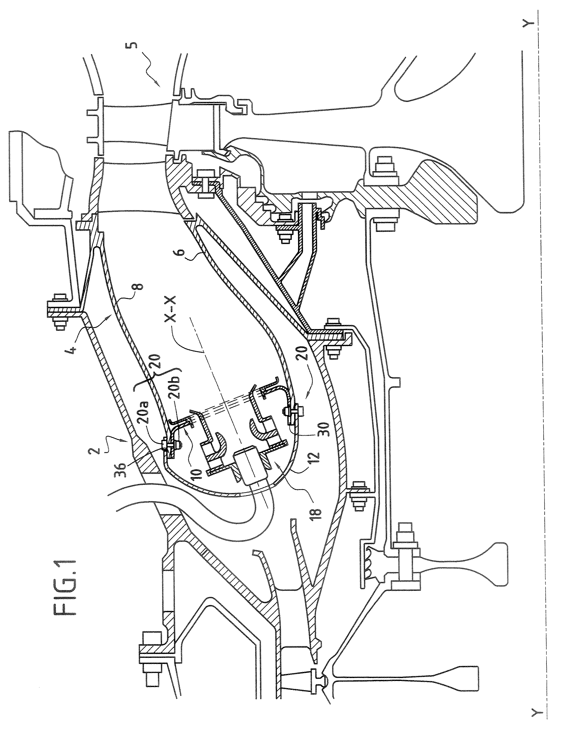
[0019]FIGS. 1 to 4 illustrate a combustion chamber for a turbine engine according to the invention.

[0020]Such a turbine engine, for example an aeronautical one, comprises in particular a compression section (not depicted) wherein air is compressed before being injected into a chamber housing 2, and then into a combustion chamber 4 mounted inside the latter.

[0021]The compressed air is introduced into the combustion chamber and mixed with fuel before being burned therein. The gases resulting from this combustion are then directed to a high-pressure turbine 5 disposed at the output of the combustion chamber.

[0022]The combustion chamber 4 is of annular type. It is made up of an inner annular wall 6 and an outer annular wall 8 which are joined upstream (with respect to the direction of flow of the combustion gases in the combustion chamber) by a transverse annular wall 10 forming the chamber bottom.

[0023]The combustion chamber also comprises an annular single-piece cowling 12 (that is to...


PUM


Abstract

A turbine engine annular combustion chamber includes inner and outer longitudinal walls connected upstream by a transverse chamber bottom and including a single-piece cowling covering the chamber bottom. Each of the longitudinal walls is inserted between corresponding flanges of the chamber bottom and of the cowling. The longitudinal walls, the chamber bottom and the cowling are assembled together by a plurality of first fixings between the longitudinal walls and the chamber bottom alternating with a plurality of second fixings distinct from the first fixings between the longitudinal walls and the cowling.

Description

BACKGROUND OF THE INVENTION[0001]The present invention relates to the general field of annular combustion chambers for turbine engines equipped with a single-piece protective cowling for the fuel injection systems.[0002]A turbine engine annular combustion chamber is generally made up of two longitudinal walls generated by revolution (an outer wall and an inner wall) which are connected upstream by a transverse wall forming the chamber bottom.[0003]The present invention relates more particularly to combustion chambers that also comprise a single-piece cowling mounted upstream of the chamber bottom. The cowling is used in particular to protect the fuel injection systems which are mounted on the chamber bottom.[0004]Assembling these different elements of the combustion chamber is carried out by means of bolt connections mounted at the inner and outer walls. More precisely, the chamber bottom and the cowling each comprise an inner flange and an outer flange on which respectively the inn...

Claims


Application Information

Patent Timeline
Patent Type & Authority Patents(United States)
IPC IPC(8): F02C7/20
CPCF23R3/10F23R3/50F23R3/60F23R2900/00017F23R2900/00005
Inventor BESSAGNET, FLORIAN ANDRE FRANCOISDE SOUSA, MARIO CESAR
Owner SN DETUDE & DE CONSTR DE MOTEURS DAVIATION S N E C M A
Why Eureka
Try Eureka