Cylinder head

a cylinder head and cylinder head technology, applied in the direction of cylinders, machines/engines, mechanical equipment, etc., can solve the problems of overheating of the oil flow inside the oil passage, oil end up being baked on the inner circumference, and the danger of oil overheating, so as to improve the durability of the head bolt insertion hole boss

a cylinder head and cylinder head technology, applied in the direction of cylinders, machines/engines, mechanical equipment, etc., can solve the problems of overheating of the oil flow inside the oil passage, oil end up being baked on the inner circumference, and the danger of oil overheating, so as to improve the durability of the head bolt insertion hole boss

US7757654B2Inactive Publication Date: 2010-07-20TOYOTA JIDOSHA KK

Image

  • Cylinder head
  • Cylinder head
  • Cylinder head

Examples


Embodiment Construction

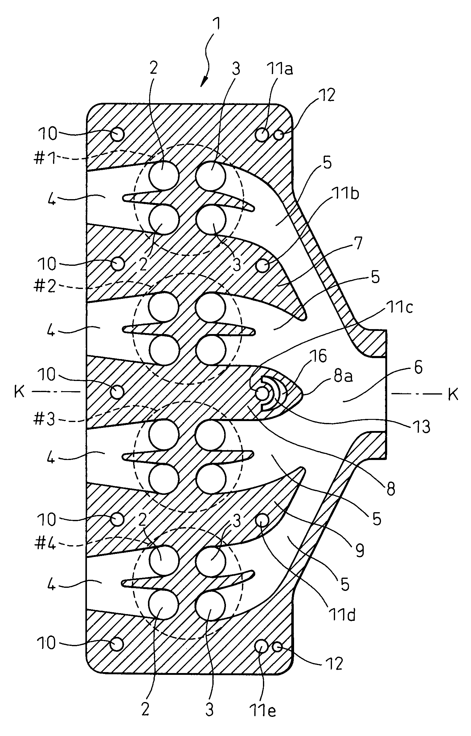
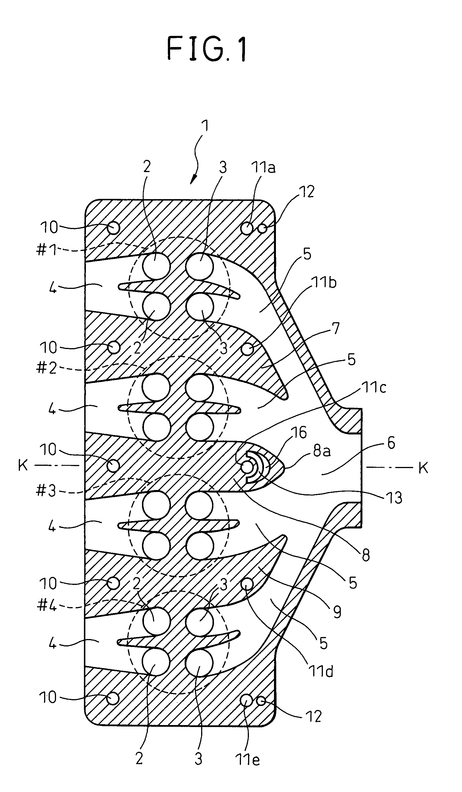
[0019]FIG. 1 is a cross-sectional plan view of a cylinder head 1 cast integrally from for example an aluminum alloy. Note that in FIG. 1, the circles shown by the broken lines show the positions of the No. 1 cylinder #1, No. 2 cylinder #2, No. 3 cylinder #3, and No. 4 cylinder #4. Therefore, it will be understood that the internal combustion engine provided with the cylinder head 1 shown in FIG. 1 is an in-line four-cylinder internal combustion engine. In FIG. 1, 2 indicate valve ports opened and closed by intake valves, while 3 indicate valve ports opened and closed by exhaust valves. Therefore, it will be understood that each of the cylinders #1, #2, #3, and #4 is provided with a pair of intake valves and a pair of exhaust valves.

[0020]Note that the cylinder head 1 is actually formed with cooling water passages extending along complicated paths, support parts of the valve mechanisms, insertion holes for the spark plugs, insertion holes for the fuel injectors, etc., but these are o...


PUM


Abstract

A cylinder head in which a partition wall for separating exhaust ports of adjoining cylinders extends from between these adjoining cylinders to an exhaust merging portion and the partition wall is formed with a head bolt insertion hole inside it, an oil passage is formed in the partition wall between the front end of the partition wall facing the exhaust merging portion and the head bolt insertion hole, and a heat insulating layer is formed inside the partition wall between the front end of the partition wall and the oil passage.

Description

BACKGROUND OF THE INVENTION[0001]1. Field of the Invention[0002]The present invention relates to a cylinder head.[0003]2. Description of the Related Art[0004]Known in the art is a cylinder head where exhaust ports of adjoining cylinders are gathered together at an exhaust merging portion inside the cylinder head, a partition wall separating the exhaust ports of these adjoining cylinders extends from between these adjoining cylinders to the exhaust merging portion, a head bolt insertion hole is formed inside the partition wall, and an oil passage is formed inside the partition wall between the front end of the partition wall facing the exhaust merging portion and the head bolt insertion hole (see Japanese Patent No. 3605521). In an internal combustion engine provided with this cylinder head, the temperature of the exhaust merging portion where the exhaust gas is collected from the cylinders becomes particularly high, so the temperature near the front end of the partition wall facing ...

Claims


Application Information

Patent Timeline
20 Jul 2010
Publication
US7757654B2
IPC
F02F1/36; F02F1/42
CPC
F02F1/4264
Inventors
NAGAFUCHI, HIROKI; ITOU, TOSHIO