Planer with carriage locking mechanism

a locking mechanism and planer technology, applied in the field of thickness planers, can solve the problems of reducing the stability of the locking carriage, and reducing the movement and vibration of the cutting head, so as to improve the locking mechanism and enhance the performance of the planer. , the effect of enhancing the stability of the present carriag

Inactive Publication Date: 2010-07-20
LIAO CHIH HUNG
View PDF8 Cites 2 Cited by
  • Summary
  • Abstract
  • Description
  • Claims
  • Application Information

AI Technical Summary

Benefits of technology

[0010]The above-listed needs are met or exceeded by the present planer including an improved carriage locking mechanism. Opposing movable lock plates are associated with a base of the planer and are moved toward each other to firmly engage carriage holding support columns to secure the carriage in position during operation. The enhanced stability of the present carriage reduces the movement and vibration of a cutting head on the carriage, as well as the carriage itself, which enhances the performance of the planer.

Problems solved by technology

Otherwise, vibration and movement of the carriage during the planing operation may produce undesired “snipe” or localized variations in the workpiece thickness.
This undesired vibration and movement is especially prevalent when the workpiece is entering or exiting the thickness planer, i.e. at the beginning and end of a cut.
It has been found that the close proximity of the locking mechanism to the cutting head likely reduces stability when locking the carriage.
Existing carriage locks such as those described above, however, fail to produce a mechanical clamping action that reduces the amount of force necessary to lock the carriage, compared to the holding strength of the locks.
Further, because existing carriage locks rely upon resiliently deflected members, these mechanisms fatigue over time and become less effective at securing the carriage.

Method used


Image

  • Planer with carriage locking mechanism
  • Planer with carriage locking mechanism
  • Planer with carriage locking mechanism

Examples


Embodiment Construction

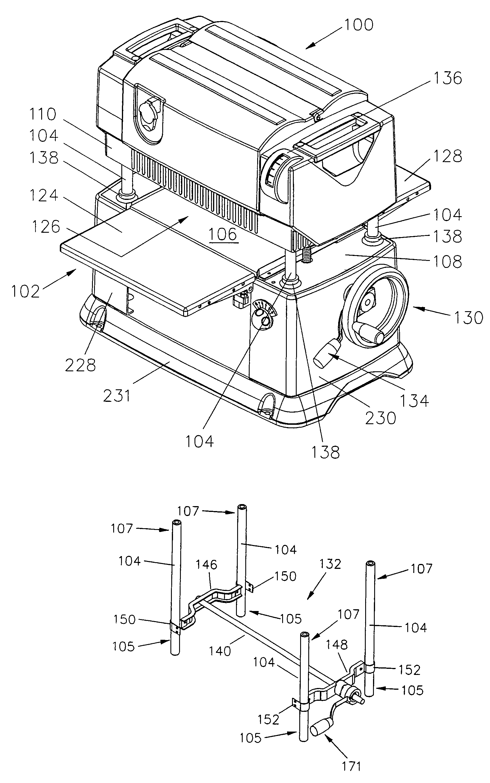
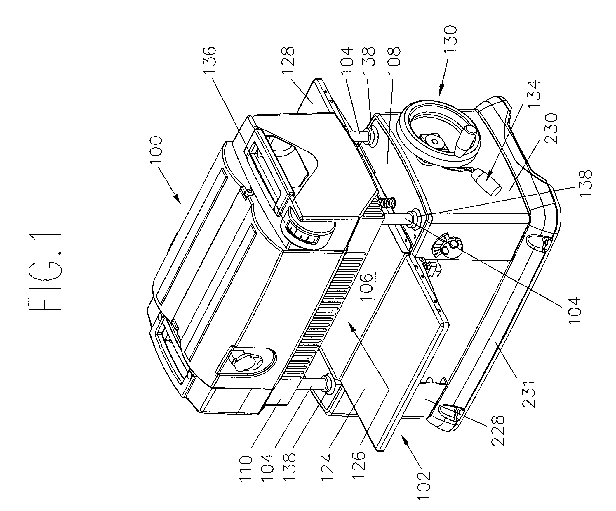
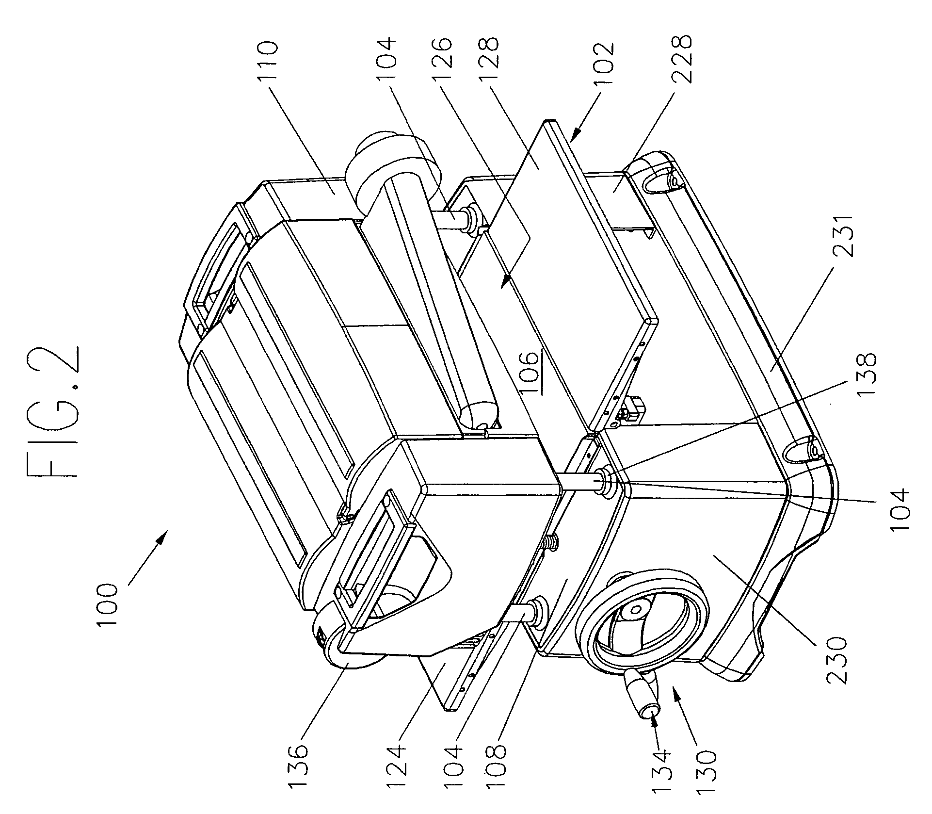
[0024]The invention relates to an apparatus for planing a workpiece to a given thickness such as the thickness planer disclosed by U.S. Pat. No. 6,585,017, the subject matter of which is incorporated herein by reference. The present thickness planer includes a carriage locking mechanism configured for reducing snipe, carriage vibration, and carriage movement by locking the cutting head on the carriage in a secure position. Snipe is a change in the thickness at either end of the planed board caused by an uneven force on the cutting head that most often occurs when a workpiece is entering or leaving the planer. By securely locking the carriage in place, movement and vibration of the carriage are reduced compared to conventional planers.

[0025]Referring now to FIGS. 1-4, a thickness planer generally indicated as 100 includes a base 102 and a plurality of support columns 104 that are movably mounted to the base as described in more detail below. The base 102, which is generally the botto...


PUM

PropertyMeasurementUnit
thicknessaaaaaaaaaa
clamping forceaaaaaaaaaa
holding forceaaaaaaaaaa

Abstract

A locking mechanism for a thickness planer having a base and a carriage with a cutting head. The carriage is mounted to a plurality of support columns movably attached to the base. The locking mechanism includes a first lock plate associated with the base and positioned adjacent to a first pair of the support columns and a second lock plate associated with the base and positioned adjacent to a second different pair of the support columns. An actuator is coupled to the first lock plate and the second lock plate and is configured for causing the first lock plate to engage the first pair of the support columns and the second lock plate to engage the second pair of the support columns to exert a clamping force by moving the first and second lock plates towards each other to firmly secure the carriage in position.

Description

BACKGROUND OF THE INVENTION[0001]The invention relates to a thickness planer and more specifically, to a thickness planer having a carriage locking mechanism that reduces vibration and movement of the carriage during a planing operation.[0002]Planing is the removal of wood from a surface or face of a board so as to make it flat, uniform, and smooth. In woodworking, planing is a common operation that is used in manufacturing cabinets, tables and other wood products.[0003]Conventional thickness planers include a base having four perpendicularly mounted columns. A carriage is supported on the support columns and includes a rotating cutting head. The cutting head has at least one cutting knife which, when rotated, removes a designated amount of material from a workpiece passing through the planer.[0004]Most thickness planers include a lead screw for adjusting the height or distance of the carriage above the base. Since the cutting head is rotatably attached to the carriage, the height o...

Claims


Application Information

Patent Timeline
Patent Type & Authority Patents(United States)
IPC IPC(8): B27C1/00
CPCB27C1/04B27C1/12B27C1/14Y10T409/308624Y10T409/30812
Inventor LIAO, CHIH HUNG
Owner LIAO CHIH HUNG
Why Eureka
Try Eureka