Supporting structure for fuel tank and automobile assembling method

a technology for supporting structures and fuel tanks, which is applied in the direction of tank vehicles, transportation and packaging, transportation items, etc., can solve the problems of reducing the rigidity of the subframe supporting the suspension arms or the rigidity of the mounting points of the suspension arms on the vehicle body, and affecting the comfort of the cabin of the vehicle, so as to ensure the tank capacity, the effect of reducing the rigidity of the subfram

Inactive Publication Date: 2010-07-20
HONDA MOTOR CO LTD
View PDF10 Cites 8 Cited by
  • Summary
  • Abstract
  • Description
  • Claims
  • Application Information

AI Technical Summary

Benefits of technology

[0007]It is therefore an object of the present invention to provide a supporting structure for a fuel tank which can sufficiently ensure the tank capacity of the fuel tank without reducing the rigidity of a subframe.
[0008]In accordance with an aspect of the present invention, there is provided a supporting structure for a fuel tank in a vehicle including a suspension arm fixing structure provided under the floor of a vehicle body and having a statically sufficient rigidity; a fuel tank located so as to partially overlap the suspension arm fixing structure in the longitudinal direction of the vehicle; and a supporting member provided under the fuel tank so as to extend in the lateral direction of the vehicle, the supporting member being detachably fastened to the suspension arm fixing structure to bring the fuel tank into pressure contact with the floor of the vehicle body by fixing the fuel tank; the supporting member serving also as a reinforcing member for imparting rigidity to the suspension arm fixing structure so that the suspension arm fixing structure can sufficiently sustain a dynamic load during running of the vehicle.
[0009]With this arrangment, the supporting member for supporting the fuel tank serves also as a reinforcing member for imparting rigidity to the suspension arm fixing structure. Accordingly, the supporting structure for the fuel tank can be rationalized, and the tank capacity can be efficiently ensured without any adverse effect on the cabin comfort of the vehicle. Further, the flexibility of arrangement of rear suspension arms can be improved, so that the improvement in rear suspension performance can be expected.
[0010]In accordance with another aspect of the present invention, there is provided a supporting structure for a fuel tank in a vehicle including a suspension arm fixing structure provided under the floor of a vehicle body and having a statically sufficient rigidity; a fuel tank located so as to partially overlap the suspension arm fixing structure in the longitudinal direction of the vehicle; and a supporting member provided under the fuel tank so as to extend in the lateral direction of the vehicle, the supporting member being detachably fastened to the suspension arm fixing structure to hold the fuel tank in cooperation with a part of the suspension arm fixing structure; the supporting member serving also as a reinforcing member for imparting rigidity to the suspension arm fixing structure so that the suspension arm fixing structure can sufficiently sustain a dynamic load during running of the vehicle.
[0014]According to this automobile assembling method, the fuel tank is mounted to the suspension module already mounted to the vehicle body, so that the mountability of the fuel tank can be improved.

Problems solved by technology

However, the above-mentioned arrangement in the related art has a problem such that the tank capacity of the fuel tank cannot be ensured and the fuel tank is located at a position where the volumetric efficiency is low, causing an increase in weight of the fuel tank and an adverse effect on the cabin comfort of the vehicle.
If the tank capacity of the fuel tank is intended to be ensured with a high volumetric efficiency, it is difficult to ensure the rigidity of the subframe for supporting the suspension arms or the rigidity of suspension arm mounting points on a vehicle body.

Method used


Image

  • Supporting structure for fuel tank and automobile assembling method
  • Supporting structure for fuel tank and automobile assembling method
  • Supporting structure for fuel tank and automobile assembling method

Examples


Embodiment Construction

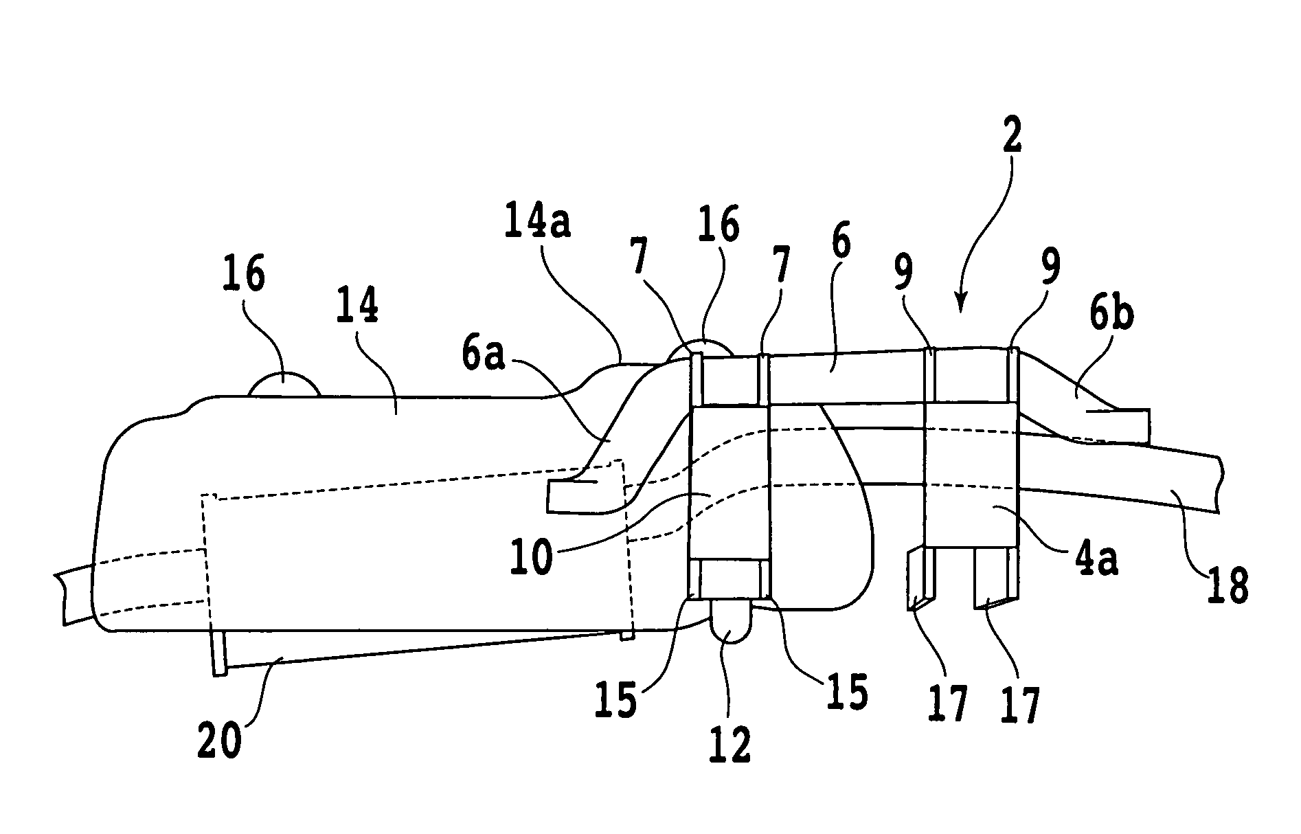
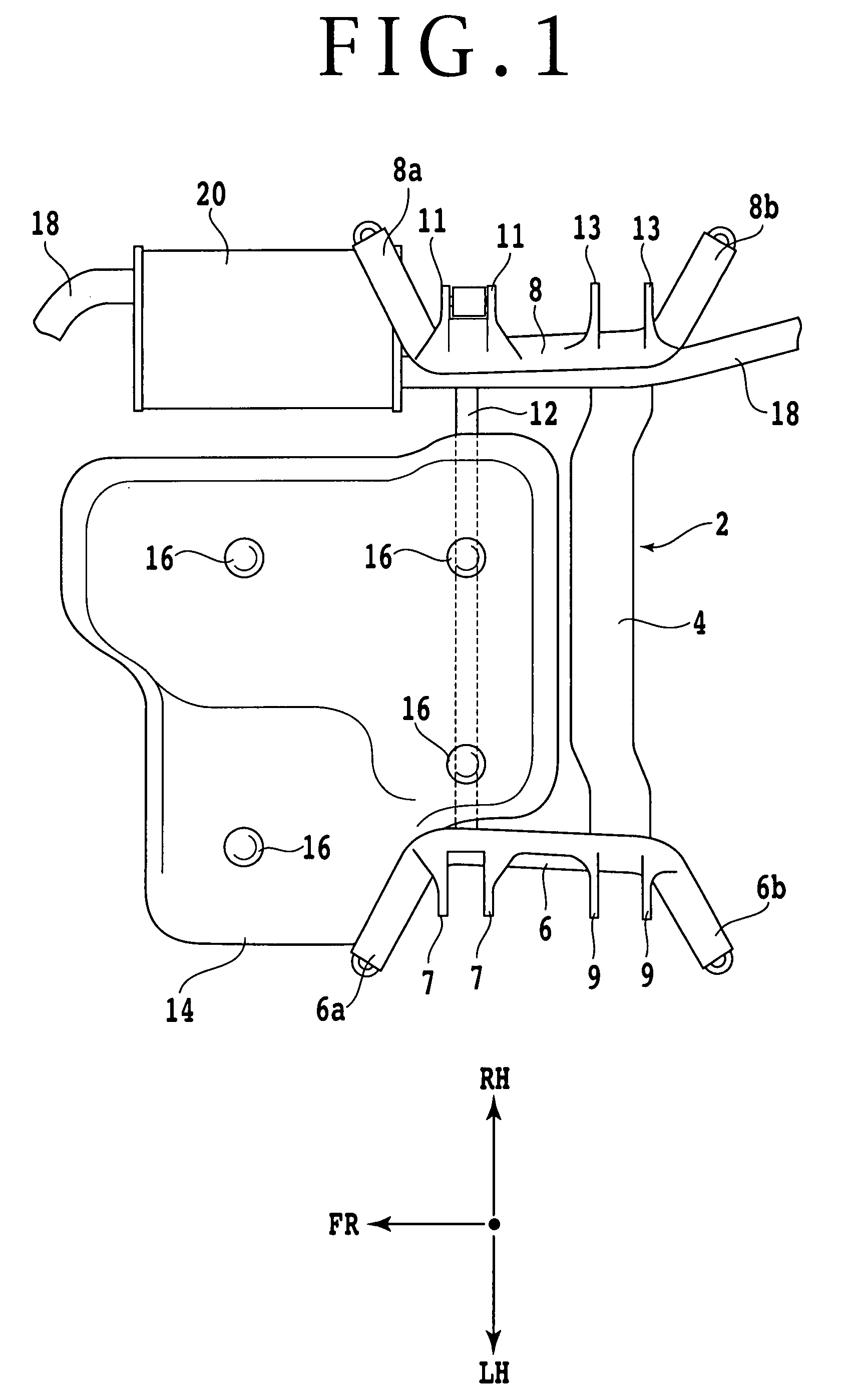
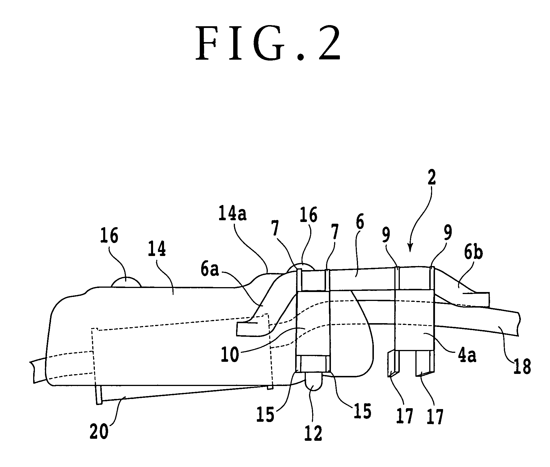
[0030]Some preferred embodiments of the present invention will now be described in detail with reference to the drawings. Referring first to FIGS. 1 to 4, there is shown a supporting structure for a fuel tank according to a first preferred embodiment of the present invention. FIG. 1 is a top plan view of the supporting structure, FIG. 2 is a left side elevation of the supporting structure, and FIG. 3 is a bottom plan view of the supporting structure. In FIGS. 1 and 3, FR, RH, and LH denote front, right, and left sides of a vehicle on which the fuel tank is mounted, respectively.

[0031]Reference symbol 2 generally denotes a subframe. The subframe 2 is composed of a lateral member 4 extending in the lateral direction of the vehicle and a pair of longitudinal members 6 and 8 extending in the longitudinal direction of the vehicle. The lateral member 4 and the longitudinal members 6 and 8 are integrally connected with each other. The longitudinal member 6 has opposite end portions 6a and ...


PUM


Abstract

A supporting structure for a fuel tank in a vehicle includes a suspension arm fixing structure provided under the floor of a vehicle body and having a statically sufficient rigidity, the fuel tank being located so as to partially overlap the suspension arm fixing structure in the longitudinal direction of the vehicle, and a supporting member provided under the fuel tank so as to extend in the lateral direction of the vehicle being detachably fastened to the suspension arm fixing structure to bring the fuel tank into pressure contact with the floor of the vehicle body by fixing the fuel tank. The supporting member serves also as a reinforcing member for imparting rigidity to the suspension arm fixing structure so that the suspension arm fixing structure can sufficiently sustain a dynamic load during running of the vehicle.

Description

BACKGROUND OF THE INVENTION[0001]1. Field of the Invention[0002]The present invention relates to a supporting structure for a fuel tank mounted on a vehicle and an automobile assembling method for mounting the fuel tank.[0003]2. Description of the Related Art[0004]Generally, a fuel tank in a vehicle is located under a rear seat, and such a layout is adopted in various types of vehicles. For example, Japanese Patent Laid-open No. Hei 6-286484 discloses a supporting structure for a fuel tank such that the fuel tank is mounted to a subframe to subassemble a rear suspension module, which is in turn mounted to a main frame. The supporting structure disclosed in this publication is intended to increase a substantial capacity of the fuel tank by setting the mounting position of a breather pipe with respect to the fuel tank to a high position. The fuel tank is supported by the subframe under the rear seat.[0005]Further, Japanese Patent Laid-open No. 2000-255448 discloses a rear subframe str...

Claims


Application Information

Patent Timeline
Patent Type & Authority Patents(United States)
IPC IPC(8): B60P3/22
CPCB60K15/063B60K15/067B60K13/04
Inventor ISAYAMA, AKIRAOKU, YASUNORIKUBO, NOBUOYANAGIDA, TAKUYA
Owner HONDA MOTOR CO LTD
Why Eureka
Try Eureka