Endoscope with relief of axial loading

a technology of axial loading and endoscope, which is applied in the field of thin-walled endoscopes, can solve the problems of degrading the viewed image, affecting the quality of the viewed image, and affecting the operation

Active Publication Date: 2010-07-20
INTUITIVE SURGICAL OPERATIONS INC
View PDF17 Cites 2 Cited by
  • Summary
  • Abstract
  • Description
  • Claims
  • Application Information

AI Technical Summary

Benefits of technology

[0012]Therefore it is an object of this invention to provide an endoscope that incorporates a tube-in-a-tube construction with minimal risk of damage during repair and / or manufacture.
[0013]Another object of this invention is to provide an endoscope that incorporates a tube-in-a-tube construction to provide an endoscope that minimizes the risk of undue axial forces deforming a tubular sheath in an optics subassembly.
[0014]Yet another object of this invention is to provide an endoscope that incorporates a tube-in-a-tube construction to provide an endoscope that minimizes the risk of undue axial forces deforming an optics subassembly when the tubular sheath is thin.
[0015]Still another object of this invention is to provide an endoscope that is easy to manufacture and facilitates necessary adjustments during manufacture while minimizing the risk of deforming the tubular sheath of an optics subassembly.
[0016]In accordance with this invention, an endoscope having distal and proximal ends includes an outer housing subassembly with a lumen therethrough and an optics subassembly in said lumen including a tubular sheath. First and second positioners are associated with the optics housing subassembly and the outer housing subassembly, respectively. A fixing structure fixes the positioning structures thereby to prevent significant axial loading of the tubular sheath.
[0017]In accordance with another aspect of this invention an endoscope having distal and proximal ends comprises an outer housing subassembly and an optics subassembly. The outer housing subassembly has a central lumen therethrough. The optics subassembly lies in the lumen and includes a tubular sheath and a plurality of optical elements. The tubular sheath has sealed windows at each of the distal and proximal ends and extends through the central lumen. The plurality of optical elements in said tubular sheath forms an image of an object and presents the image for viewing. Material intermediate the outer housing subassembly and the tubular sheath prevent displacement therebetween during normal use. First and second positioning structures are associated with the optics subassembly and the outer housing subassembly, respectively. A structure fixes the positioning structures thereby to prevent significant axial loading of the tubular sheath.

Problems solved by technology

However, in many devices the optics subassembly can be subjected to compression forces during construction, use and repair.
As the tubular sheath wall becomes thinner, the possibility arises that these compressive forces will deform or warp the tubular sheath and thereby will degrade the viewed image.

Method used


Image

  • Endoscope with relief of axial loading
  • Endoscope with relief of axial loading
  • Endoscope with relief of axial loading

Examples


Embodiment Construction

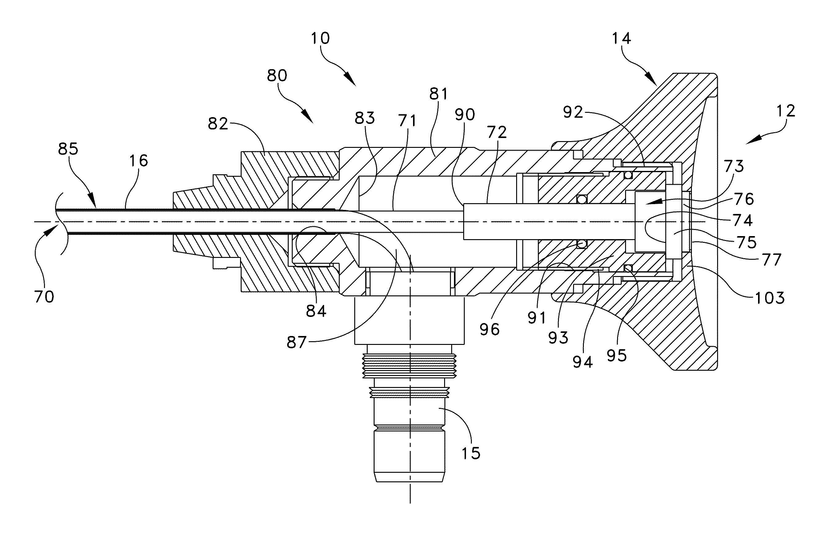
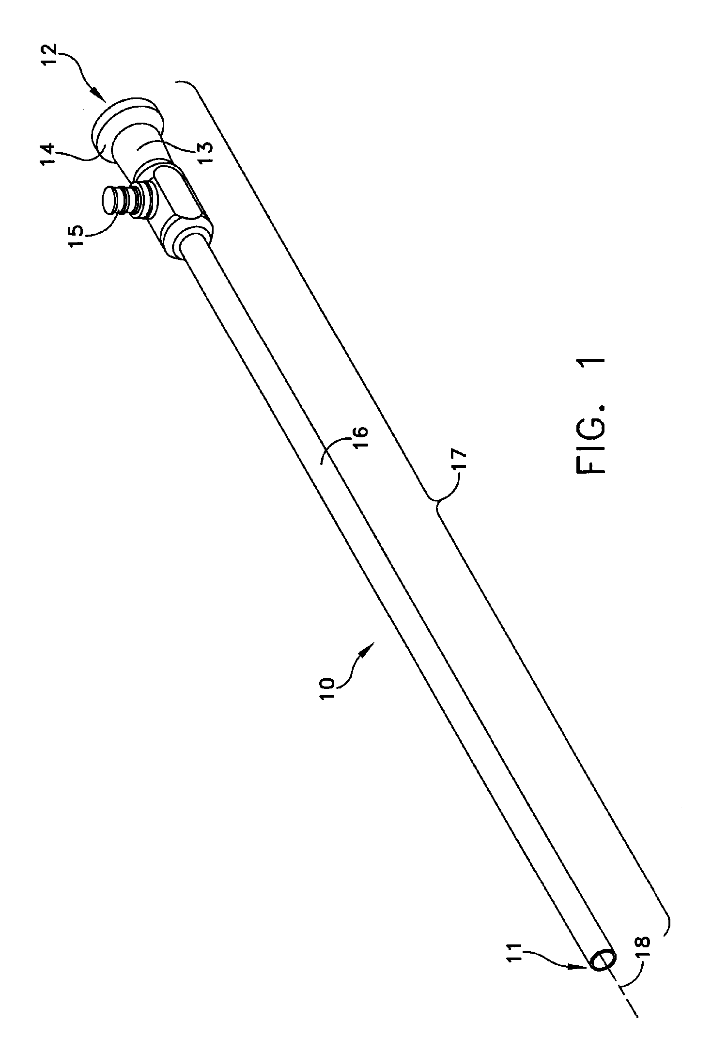
[0025]FIG. 1 depicts an endoscope 10 as it appears to medical personnel for use. It extends between a distal end 11, the end closest to the object to be imaged, and a proximal end 12, the end closest to the person using the device. This view depicts an optical body 13 with an eyecup 14 through which the image is viewed. A fiber post 15 receives an output connection from an illumination source thereby to provide light for transmission through optical fiber to illuminate the object being imaged. An outer sheath of a tube 16 extends from the optical body. All of these elements constitute components of an outer housing subassembly 17 that extends along an optical axis 18.

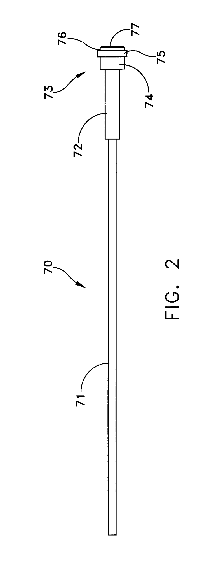
[0026]The endoscope 10 houses an optics subassembly 70 as shown in FIG. 2. The optics subassembly 70 can have any of a variety of implementations. One such implementation is depicted in U.S. patent application Ser. No. 11 / 161,934. Consequently only the exterior of the sheath 71 and a collar 72 are disclosed in FIG. 2. T...


PUM


Abstract

A rigid endoscope includes an outer housing subassembly that supports an optics subassembly. The outer housing subassembly includes concentric tubes with optical fiber for providing object illumination. The optics subassembly includes a tubular sheath sealed at both ends for carrying lenses and other optical elements. First and second positioners associated with the optics subassembly and the outer housing subassembly, respectively, limit the transfer of axial forces from the proximal end of the endoscope to the tubular sheath.

Description

CROSS REFERENCE TO RELATED APPLICATION[0001]Co-pending U.S. patent application Ser. No. 10 / 383,236 to Forkey et al. filed Mar. 6, 2003 now U.S. Pat. No. 6,955,644 granted Oct. 18, 2005 for an Autoclavable Endoscope, assigned to the same assignee as the present application; and[0002]Co-pending U.S. patent application Ser. No. 11 / 161,934 to Forkey et al. filed Aug. 23, 2005 for a Repairable Endoscope, assigned to the same assignee as the present applicationFIELD OF THE INVENTION[0003]This invention relates to endoscopes and more particularly to thin-walled endoscopes subject to damage from undue axial forces.DESCRIPTION OF RELATED ART[0004]Endoscopes come in two basic forms. In one form the endoscope is flexible. Optical fibers transfer an image from an optical objective to an eyepiece or other viewing device. The fibers produce image pixels of the image from the optical objective. Endoscopes of the second form are called rigid endoscopes. This invention is particularly applicable to ...

Claims


Application Information

Patent Timeline
Patent Type & Authority Patents(United States)
IPC IPC(8): A61B1/04A61B1/00A61B1/002A61B1/12
CPCA61B1/00105A61B1/00142A61B1/002A61B1/121
Inventor ROSS, ROBERT N.FORKEY, RICHARD E.
Owner INTUITIVE SURGICAL OPERATIONS INC
Why Eureka
Try Eureka