Battery voltage measurement circuit, battery voltage measurement method, and battery electric control unit

a voltage measurement and battery technology, applied in the direction of measurement using ac-dc conversion, instruments, transportation and packaging, etc., can solve the problems of deteriorating accuracy of voltage detection, difficulty in obtaining a large gain, and breakage of a whole battery assembly, so as to reduce the size of the battery ecu, high accuracy, and the effect of reducing the size of the battery

Inactive Publication Date: 2010-07-20
KEIHIN CORP
View PDF11 Cites 38 Cited by
  • Summary
  • Abstract
  • Description
  • Claims
  • Application Information

AI Technical Summary

Benefits of technology

[0010]In order to solve the above problems, the present invention has an object of providing a battery voltage measurement circuit, a battery voltage measurement method, and a battery electric control unit wherein a voltage of each of unit batteries constituting a battery assembly can be measured with high accuracy by using a common measurement circuit in a relatively simple and inexpensive configuration.

Problems solved by technology

In such a case, when one of unit batteries has a trouble and operates with an extreme low or high voltage, the unit battery having a trouble can cause corrosion or insufficient voltage resistance, which can result in the breakage of a whole battery assembly.
Therefore, it is difficult to obtain a large gain, and the accuracy of the voltage detection is deteriorated.
Furthermore, an increase of a dark current causes a problem that the accuracy of the voltage detection can not be sufficiently obtained.
Therefore, a large number of elements having high voltage resistance in both directions are necessary, which results in the increase of the cost.
However, such configuration is likely to be affected by noises due to parasitic capacity or the like.
Therefore, there easily occurs a noise, a cause of which is difficult to determine, and the configuration is likely to be affected by parasitic noises.

Method used


Image

  • Battery voltage measurement circuit, battery voltage measurement method, and battery electric control unit
  • Battery voltage measurement circuit, battery voltage measurement method, and battery electric control unit
  • Battery voltage measurement circuit, battery voltage measurement method, and battery electric control unit

Examples


Embodiment Construction

[0040]Hereinafter, embodiments of the present invention will be described in detail with reference to the attached drawings.

[0041]The same components will be denoted by the same references in the drawings.

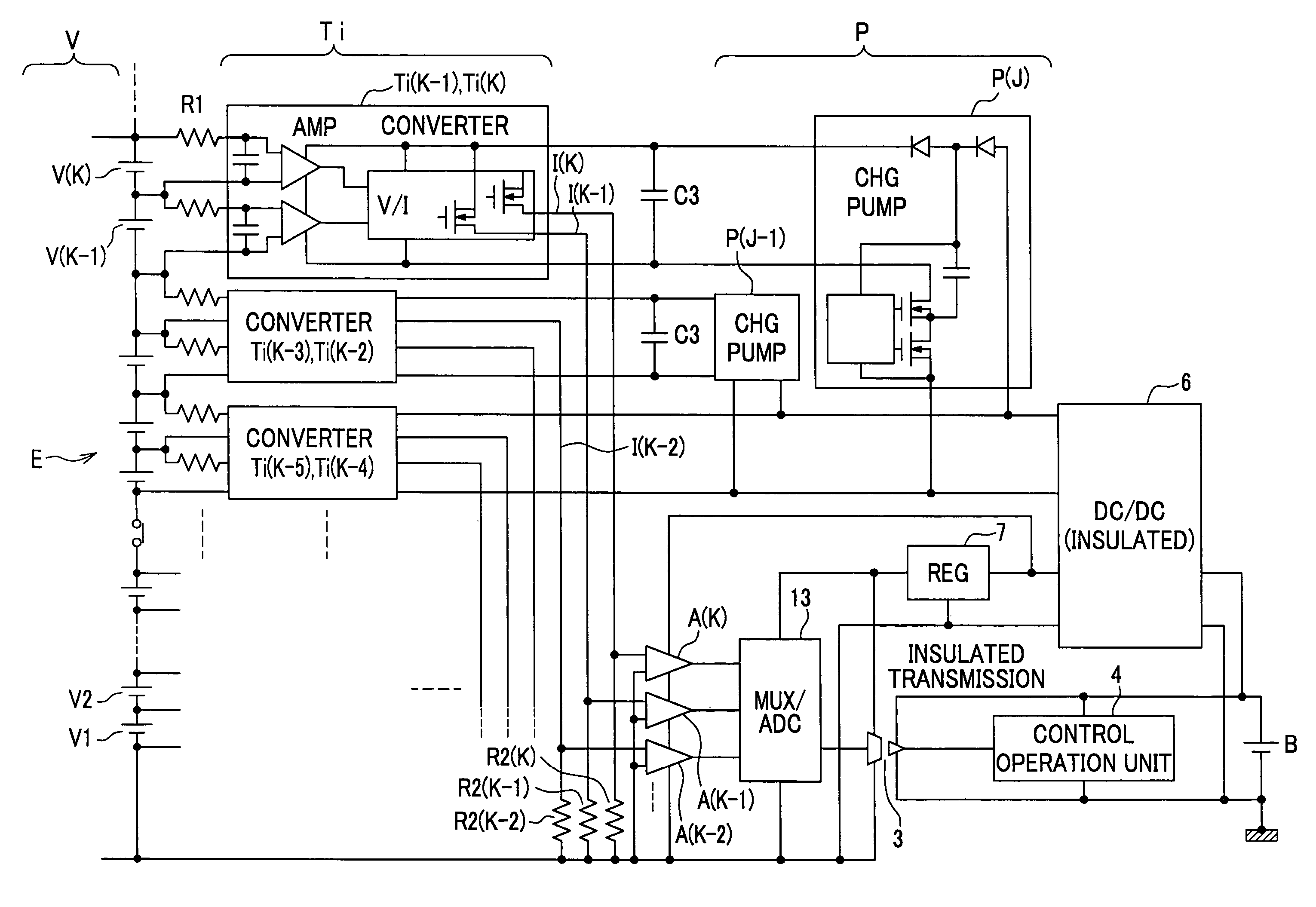
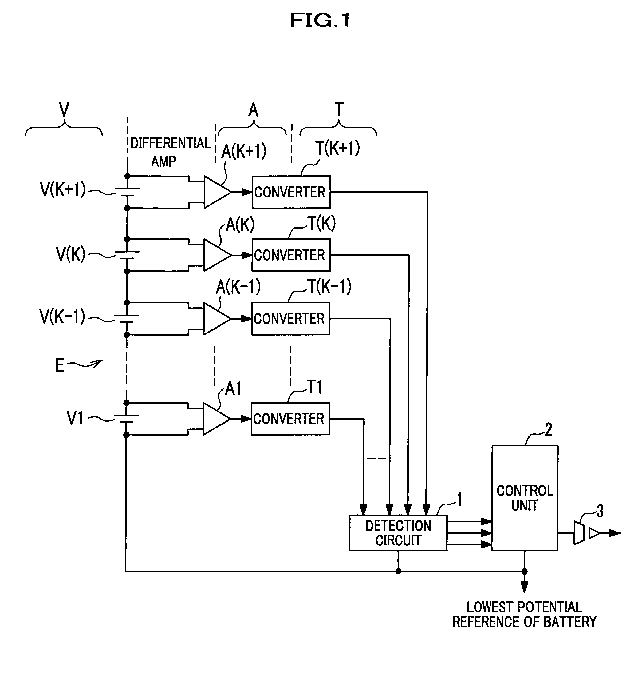
[0042]FIG. 1 is a schematic block diagram of a battery voltage measurement circuit according to an embodiment of the present invention. In FIG. 1, the reference marks V, A, and T are accompanied by characters for their identification. When K (integral number) and a number added to or subtracted from K are accompanied by the reference marks V, A, and T, the characters are indicated in parenthesis after K. The reference mark E denotes a battery assembly that is an object to be measured. The reference marks V1, . . . , V(K), . . . denote individual unit batteries constituting the battery assembly E. The reference marks A1, . . . , A(K), denote differential amplifiers (AMP) that detect a voltage of each of the unit batteries V1, . . . , V(K), . . . . The reference marks T1, . . . , T(K...


PUM

PropertyMeasurementUnit
voltageaaaaaaaaaa
voltageaaaaaaaaaa
electric potentialaaaaaaaaaa

Abstract

A voltage between both terminals of each unit battery is amplified by a differential amplifier and is then converted by a converter into a predetermined physical quantity that corresponds to the voltage between both terminals of the unit battery. The converted physical quantity is then level-shifted by a detection circuit and is converted into a voltage on a reference potential of the lowest electric potential of the battery assembly. A control unit sequentially selects the converted voltages by a multiplexer, generates serial digital signals by an A / D conversion, and then transmits the serial digital signals to a control operation unit via an isolation buffer circuit. It is, therefore, possible to provide a battery voltage measurement circuit capable of measuring a voltage of each of unit batteries constituting a battery assembly with high accuracy by using a common measurement circuit in a relatively simple and inexpensive configuration.

Description

CROSS-REFERENCE TO RELATED APPLICATION(S)[0001]This application claims the foreign priority benefit under Title 35, United States Code, §119 (a)-(d), of Japanese Patent Application No. 2006-81589, filed on Mar. 23, 2006 in the Japan Patent Office, the disclosure of which is herein incorporated by reference in its entirety.BACKGROUND OF THE INVENTION[0002]1. Field of the Invention[0003]The present invention relates to a system for measuring a voltage of each of cells constituting a battery assembly having a large number of cells, which are connected in series.[0004]2. Description of the Related Art[0005]In hybrid vehicles, electric vehicles, fuel-cell vehicles or the like, it has become common to configure a high-voltage battery assembly by connecting in series a plurality of unit batteries including rechargeable batteries or fuel cells in order to reduce the loss due to wiring resistance or reduce the size of a switching element. In the case that a fuel cell is used, for example, a ...

Claims


Application Information

Patent Timeline
Patent Type & Authority Patents(United States)
IPC IPC(8): H02J7/00H02J7/04H02J7/16G01N27/416
CPCG01R31/362G01R31/3658G01R31/396G01R31/3835
Inventor KAMATA, SEIJI
Owner KEIHIN CORP
Why Eureka
Try Eureka