
Wireless perforating gun

a perforating gun and wireless technology, applied in the direction of ammunition fuzes, lighting and heating apparatus, borehole/well accessories, etc., can solve the problems of increasing the amount of time required, hot wire no longer maintaining isolation from the ground, and live wire pinching

Active Publication Date: 2010-07-27
SCHLUMBERGER TECH CORP
View PDF17 Cites 56 Cited by
  • Summary
  • Abstract
  • Description
  • Claims
  • Application Information

AI Technical Summary

Benefits of technology

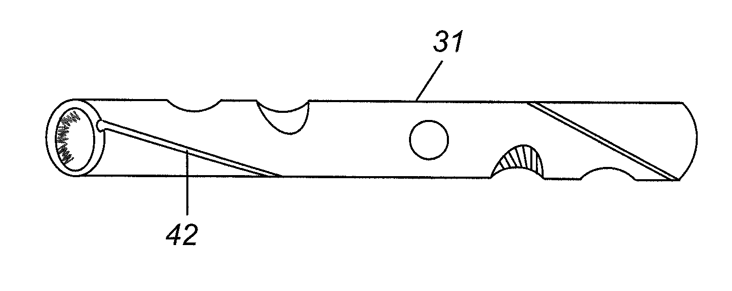
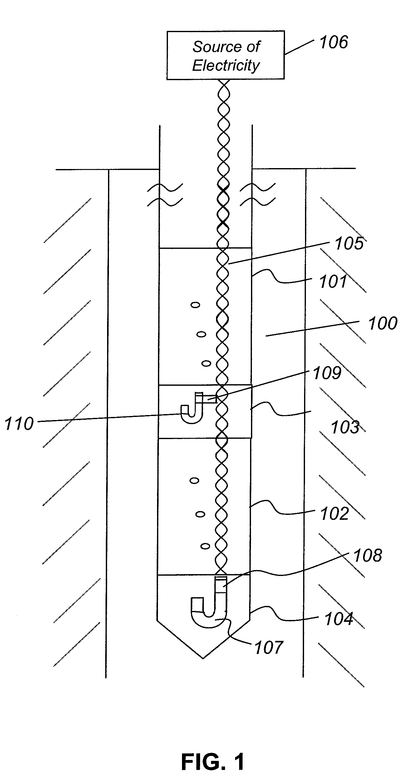
The present invention provides a perforating gun system for use in perforating the formation material proximate a wellbore. The system includes at least one perforating gun section comprising a body and a plurality of radially oriented shaped charges. The system also includes a loading tube which holds the shaped charges and the detonating cord, and which is installed in the body of the gun. The loading tube comprises at least a portion of the electrical circuit used to initiate the detonation of the charges, and may be insulated from the body of the gun using various methods such as coating or installing stand-offs. The system also includes a method for establishing an electrical circuit in the perforating gun to initiate the detonation of the shaped charges. The technical effects of the invention include improved safety and reliability in the perforating process, as well as more efficient and effective wellbore stimulation.

Problems solved by technology

It frequently occurs that the live wire gets pinched during loading or transportation or even after arming of the perforating gun.
The live wire may become an open circuit as a result of being pinched or may be shorted to ground which results in the hot wire no longer maintaining isolation from the ground.
The presence of the wires also increases the amount of time required to load a gun, and if a cable gets pinched or shorts out during the loading or transporting process, the wires must be replaced and reinstalled in the gun, which increases the time necessary for loading.
The problems with the wires that are used in activating the electrical detonators are believed to contribute significantly to quality issues with respect to wireline perforating services.

Method used


Image

  • Wireless perforating gun
  • Wireless perforating gun
  • Wireless perforating gun

Examples


Embodiment Construction

[0025]It will be appreciated that the present invention may take many forms and embodiments. In the following description, some embodiments of the invention are described and numerous details are set forth to provide an understanding of the present invention. Those skilled in the art will appreciate, however, that the present invention practiced without those details and that numerous variations from and modifications of the described embodiments may be possible. The following description is thus intended to illustrate and not to limit the present invention.

[0026]While the following description may focus on the use of a apparatus according to the present invention in a wireline perforating system, those skilled in the art will appreciate that the such apparatus may also be utilized in other types of perforating systems when selective firing of the perforating guns in the string of perforating guns is desired. The applicants intend, therefore, that the appended claims, unless express...


PUM


Abstract

A loading tube for installation in the body of a perforating gun is disclosed. The loading tube holds a plurality of shaped charges whose detonation is electrically initiated, and the loading tube, when installed in the body, comprises at least a portion of the electrical circuit used to initiate detonation the shaped charge. In one embodiment, the loading tube comprises the hot portion of the electrical circuit, the body comprises the ground portion of the electrical circuit and the loading tube and the body are insulated from one another. Alternatively, the loading tube may comprise two distinct portions of conductive material which are electrically isolated from one another where the two portions of conductive material comprise the hot and ground portions of the electrical circuit. Additionally, a loading tube according to the present invention may comprise a conductor which is disposed in the loading tube near the outer surface of the loading tube and which is insulated from the loading tube. A system is disclosed comprising a loading tube having the aforesaid characteristics and a method is provided which utilizes the loading tube as a portion of the electrical circuit to initiate detonation of the charges.

Description

BACKGROUND OF THE INVENTION[0001]1. Field of the Invention[0002]The present invention relates to method and apparatus for performing perforating operations, and, more particularly, to performing wireless perforating gun operations.[0003]2. Description of the Prior Art[0004]For purposes of enhancing production from a subterranean formation, a perforating gun typically is lowered down into a wellbore that extends through the formation. A perforating gun comprises a plurality of radially-oriented shaped charges which are detonated to penetrate and form perforations through the casing and cement into the formation proximate the wellbore. The shaped charges typically are distributed at points along a helical spiral that extends around the longitudinal axis of the perforating gun.[0005]In wireline guns, there are normally two wires that run the length of the gun string. One of these wires is a live or hot wire which is connected to a positive or negative voltage, and the other wire is a g...

Claims


Application Information

Patent Timeline
Patent Type & Authority Patents(United States)
IPC IPC(8): E21B43/116E21B43/117
CPCE21B43/1185F42D1/05
Inventor LI, HAOMINGXU, ZHENG RONGSMITHEMAN, CHANTALGAMA, CESARFAYARD, ALFREDO
Owner SCHLUMBERGER TECH CORP
Learn More