Dispensing closure with latch back

a technology of latch back and closure, which is applied in the direction of closures using stoppers, caps, liquid handling, etc., can solve the problems of difficult to close the lid and the dispensing experience is not easy, and achieves the effect of low cost and efficient operation

Active Publication Date: 2010-07-27
WESTROCK SLATERSVILLE
View PDF33 Cites 31 Cited by
  • Summary
  • Abstract
  • Description
  • Claims
  • Application Information

AI Technical Summary

Benefits of technology

[0006]The present invention preserves the advantages of existing dispensing closures while providing new advantages not found in currently available dispensing closures and overcoming many disadvantages of such currently available dispensing closures. The general concept of the present invention is to provide a dispensing closure an efficient, low-cost fashion through use of a molded single-piece plastic construction with integrally molded living hinges and integrally molded features on the closure body and cap which are engaged to maintain the lid in an open position.
[0013]It is therefore an object of the present invention to provide a one-piece low cost dispensing closure.
[0014]It is a further object of the embodiment to provide a dispensing closure which can latch back to secure a closure cap to a closure body during dispensing of a product.

Problems solved by technology

When this occurs, the lid interferes with dispensing of the product, making for a messy dispensing experience, and fouls the lid surfaces, making it difficult to close the lid.

Method used


Image

  • Dispensing closure with latch back
  • Dispensing closure with latch back
  • Dispensing closure with latch back

Examples


first embodiment

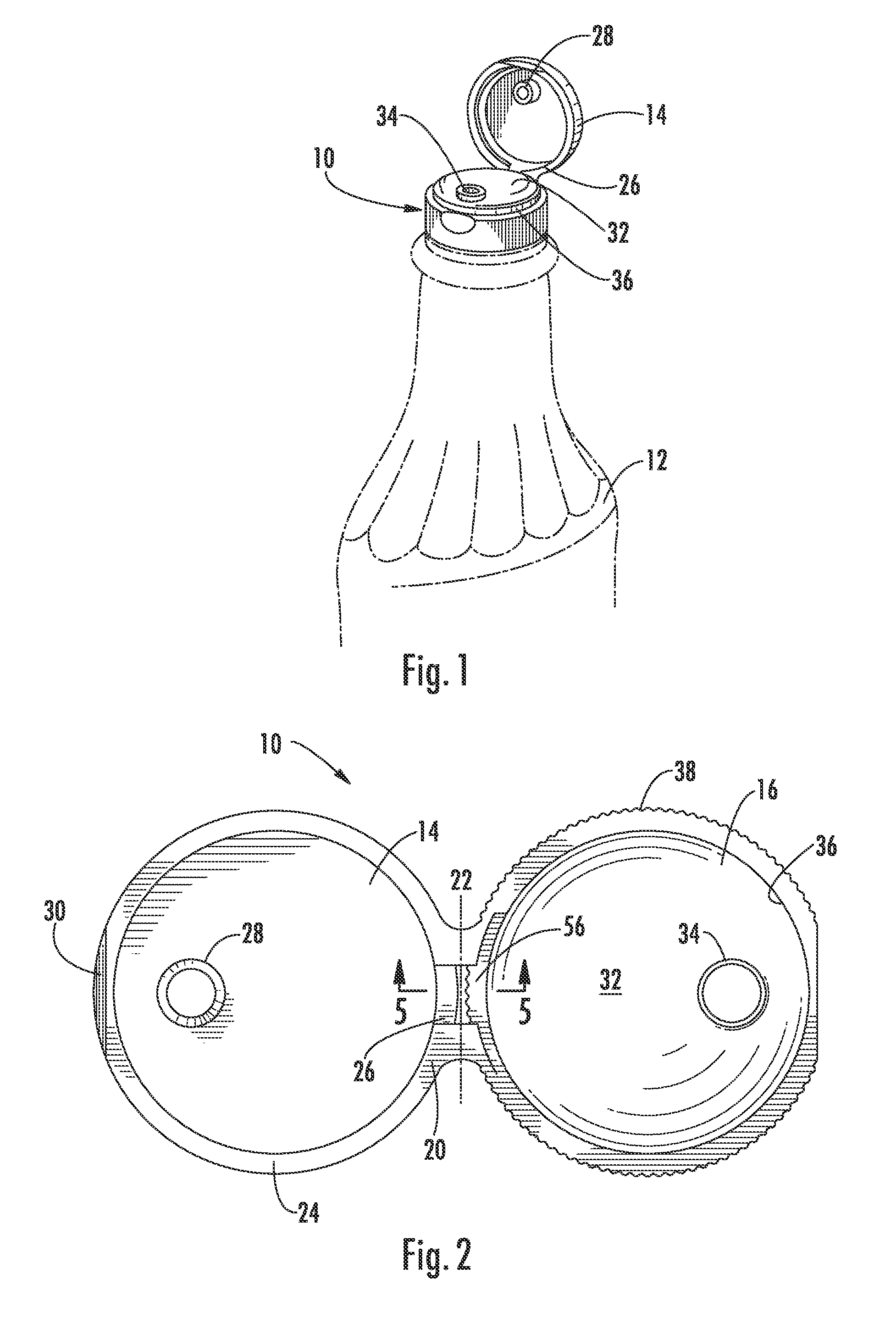
[0053]Referring now to the drawings, FIG. 1 depicts a dispensing closure constructed in accordance with the principles of the invention. The dispensing closure is generally identified at 10, and is shown secured to the upper end of the neck of container 12. Container 12 may assume the form of a plastic bottle, which may be tilted, and squeezed, to discharge its contents through closure 10.

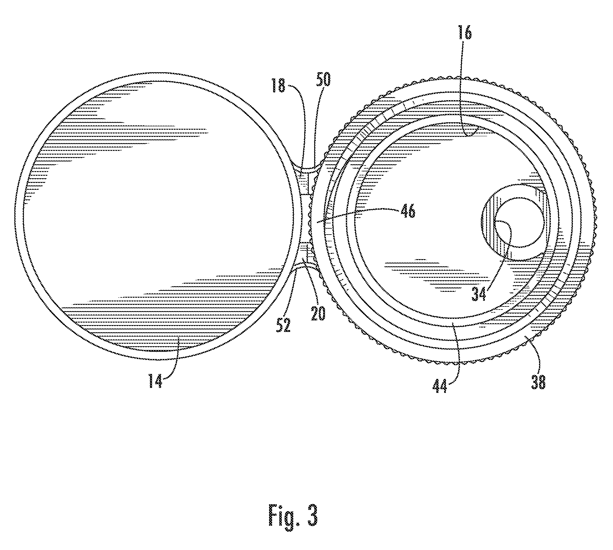
[0054]FIG. 2 shows dispensing closure 10 in its as-molded condition, prior to its securement to container 12. Closure 10 comprises sealing cap 14, a closure body 16, and a pair of hinges 18, 20 that join the sealing cap to the closure body. Sealing cap 14 is pivoted along the center line 22 of the hinges relative to closure body 16.

[0055]Sealing cap 14, as shown in FIGS. 2 and 3, includes an annular flange 24, a camming lug 26 located on flange 24 in proximity to closure body 16, and a depending peg 28. Camming lug 26 is curved, when viewed from above, and follows the contour of flange 24. Flange 2...

seventh embodiment

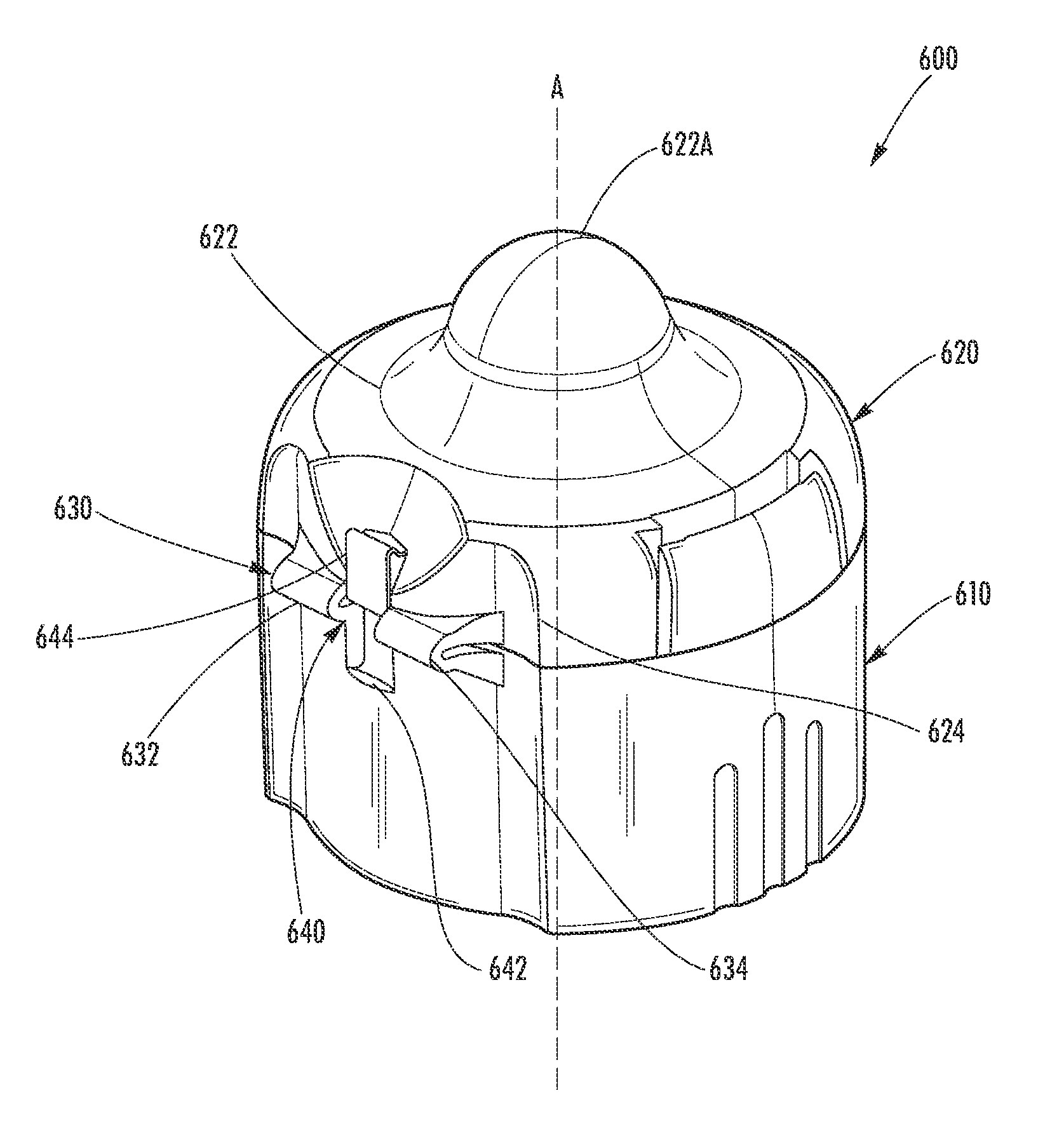
[0092]Referring now to FIGS. 28-33, the dispensing closure 600 is illustrated and includes all or many of the advantages of the previous embodiments recited above. Referring to FIG. 28, the dispensing closure 600 generally includes a closure body 610, a closure cap 620, and a hinge structure 630 for connecting the closure body 610 to the closure cap 620. The closure cap is configured to move from an open position (FIG. 29) to a closed position (FIG. 28) overlying a closure deck 670 of the closure body 610.

[0093]The seventh embodiment further includes another embodiment of the latch back mechanism 640 having a latch recess 642 defined within the closure body 610 and a latch protrusion 644 on the closure cap 620, which will allow the cap 620 to be retained in an open position during dispensing of product. See FIG. 29 for fully open, latched position.

[0094]The dispensing closure 600 may be secured to an upper end of a neck of a container (not shown). The container may assume the form o...


PUM


Abstract

A closure body has a closure deck with a dispensing orifice. A lower peripheral skirt depends from the closure deck and is configured to be mounted on a container. A closure cap has an upper wall and a wall flange which depends from the upper wall. A hinge structure joins the wall flange to the lower peripheral skirt. A latch recess is defined within the lower peripheral skirt. A latch protrusion is located on the wall flange of the cap and positioned respectively positioned above the latch recess when closure cap is in a closed position. The latch protrusion and the latch recess define interfitting mating formations which engage to secure the cap to the closure body when the closure cap is in an open position.

Description

CROSS REFERENCE TO RELATED APPLICATIONS[0001]This continuation-in-part application is related to and claims priority from earlier filed, U.S. Non-Provisional patent application Ser. No. 11,876,067 filed Oct. 22, 2007, which claims priority from earlier filed U.S. Provisional Patent Application No. 60 / 895,084 filed Mar. 15, 2007, and earlier filed U.S. Non-Provisional patent application Ser. No. 10 / 960,179 filed Oct. 7, 2004 now U.S. Pat. No. 7,322,493, and earlier filed U.S. Provisional Patent Application No. 60 / 587,518 filed Jul. 13, 2004, and earlier filed U.S. Provisional Patent Application No. 60 / 509,523 filed Oct. 9, 2003 all of which are incorporated herein by reference.BACKGROUND OF THE INVENTION[0002]The present application is related to dispensing closures for containers and more specifically to a dispensing closure that includes a latch back mechanism to restrain the cap when dispensing the contents of the container.[0003]Dispensing containers are used in a variety of indu...

Claims


Application Information

Patent Timeline
Patent Type & Authority Patents(United States)
IPC IPC(8): B65D47/00
CPCB65D47/0819B65D47/0823B65D47/0838B65D2251/1008B65D2251/20
Inventor SKILLIN, CLIFFORD W.
Owner WESTROCK SLATERSVILLE
Why Eureka
Try Eureka