
Cleaning method

a cleaning method and cleaning method technology, applied in the field of cleaning methods, can solve the problems of high cost, large amount of sludge, and high cost of ultrasonic cleaning equipment, and achieve the effects of low cost, enhanced cleaning effect of gas-dissolved water, and high cleanliness

Inactive Publication Date: 2015-09-08
KURITA WATER INDUSTRIES LTD
View PDF14 Cites 5 Cited by
  • Summary
  • Abstract
  • Description
  • Claims
  • Application Information

AI Technical Summary

Benefits of technology

[0019]The present invention makes it possible to clean a subject by high-pressure jet cleaning or two-fluid cleaning using gas-dissolved water so that the subject has high cleanliness in a resource-saving, low-cost, and efficient way.
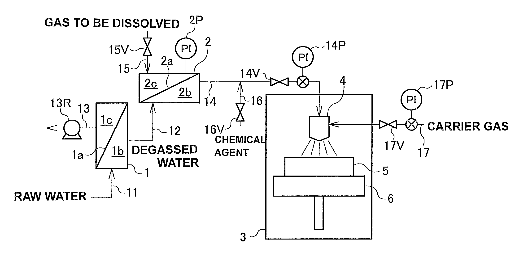
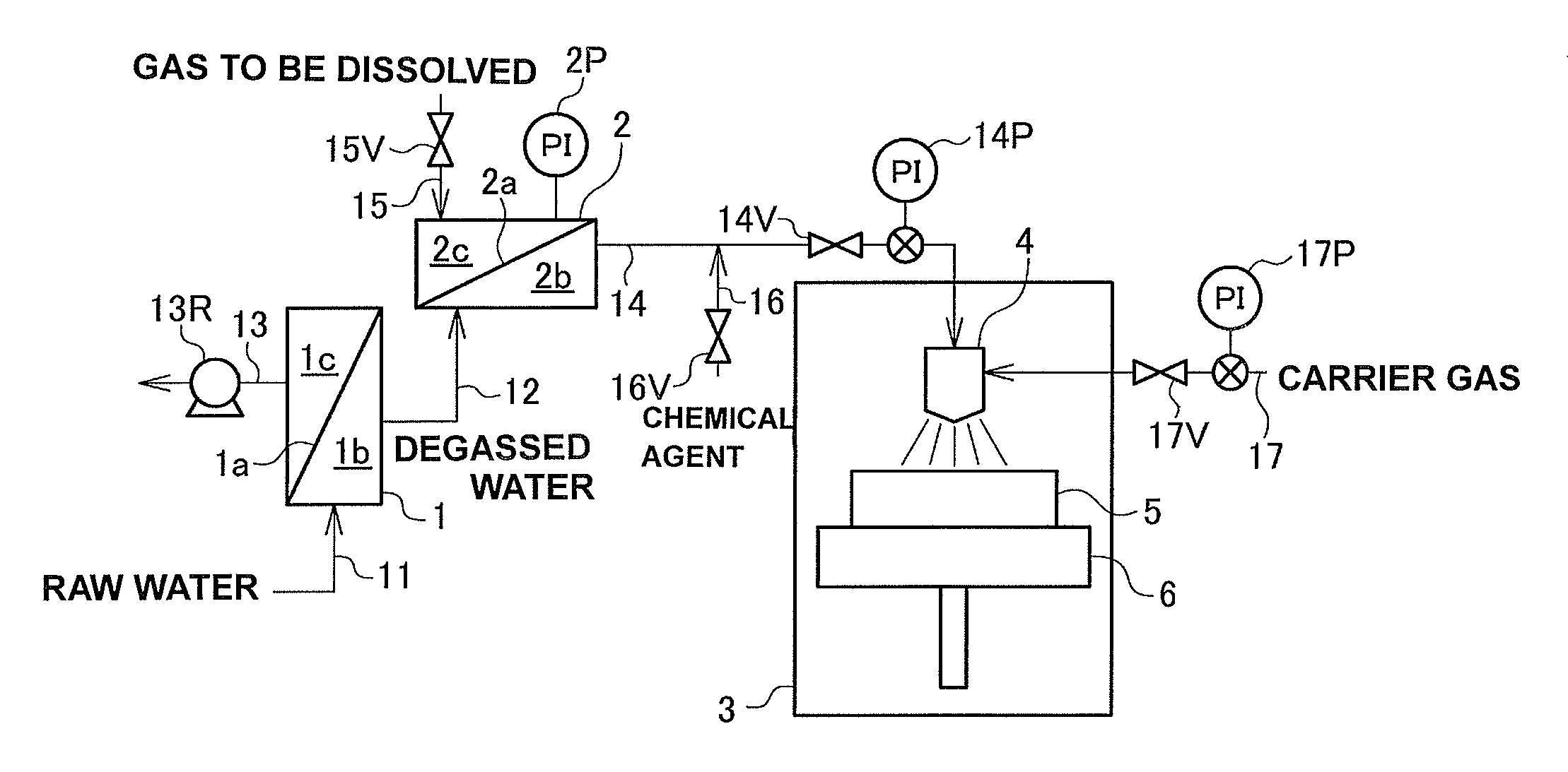
[0020]In the present invention, as mentioned above, a gas is dissolved in the cleaning liquid in a quantity equal to or more than the saturation solubility. Once the supersaturated cleaning liquid is jetted and released as cleaning droplets from the nozzle, the gas dissolved therein grows into active bubbles while acting on the surface of the subject to be cleaned. Besides the physical cleaning effect of the cleaning droplets colliding with the surface of the subject, the scrubbing effect of the bubbles, the impact force generated with the collisions of the bubbles, the adsorbing force that works on the gas-liquid boundary, and other physicochemical cleaning actions are applied to the subject and the sludge materials such as fine particles on the surface of the subject. As a result, the gas-dissolved water is enhanced in its cleaning effect including removing fine particles.
[0021]In the present invention, the dissolved gas is preferably at least one selected from the group consisting of nitrogen gas, oxygen gas, carbon dioxide gas, hydrogen gas, ozone gas, purified air, and rare gas. These gases for dissolution are preferably dissolved to achieve a degree of oversaturation of 1 to 5 times as high as their own saturation solubility.
[0022]The liquid for dissolving the gas therein is preferably pure water or ultrapure water. Considering the gas dissolution efficiency and other factors, it is preferred that the liquid for dissolving the gas therein is degassed.
[0023]The cleaning liquid used in the present invention may contain at least one chemical agent selected from the group consisting of alkalis, acids, chelating agents, and surfactants. The presence of these kinds of chemical agents will lead to a further improved cleaning effect.

Problems solved by technology

Such waste water is required to be treated by neutralization, segmentation or the like which needs a high cost and produces a large amount of sludge.
The cleaning effect of gas-dissolved water is admittedly higher than the cleaning effect of water containing no dissolved gases, but fine particles are not fully removed by a high with high-pressure jet cleaning process or a two-fluid cleaning process alone.
However, an ultrasonic cleaning equipment is expensive and thus causes an increased cleaning cost.
Furthermore, cleaning glass substrates or the like with gas-dissolved water and ultrasonic requires a large amount of cleaning water, since ultrasonic is irradiated to the substrate using a squall nozzle or the like.
However, the high-pressure jet cleaning process or the two-fluid cleaning process with gas-dissolved water can not achieve a sufficient cleaning effect.

Method used


Image

  • Cleaning method
  • Cleaning method

Examples


example 1

[0075]A cleaning test was conducted using a cleaning apparatus as shown in FIG. 1 with a contaminated wafer detailed below as a subject to be cleaned.

[0076]

[0077]Oxide-coated wafer contaminated by alumina slurry: six-inch silicon wafer contaminated by alumina slurry after treated with ozonated water for hydrophilizing the wafer surface. The number of fine particles (fine particles of 0.12 μm or larger) on the wafer surface after contamination was 6000 to 7000 particles / wafer.

[0078]The gas-dissolved water used was oxygen-gas-dissolved water prepared by degassing ultrapure water at the degassing membrane module (the pressure of the gas-phase room of the degassing membrane module was 5 kPa, equivalent to 95% degassing) and dissolving oxygen gas at the gas-dissolving membrane module to achieve a saturation factor of 3 (the pressure of the gas-phase room of the gas-dissolving membrane module was 0.2 MPa, equivalent to a saturation factor of 3).

[0079]The nozzle used for cleaning and other...

example 2

[0092]The contaminated wafer was cleaned and the fine particle removal rate was calculated in the same way as Example 1 except that cleaning water was prepared by adding ammonia to the oxygen-gas-dissolved water at a concentration of 1 mg / L (pH 9.4). The result is shown in Table 1.

examples 3 to 6

[0094]The contaminated wafer was cleaned and the fine particle removal rate was calculated in the same way as Example 1 except that the pressure of the gas-phase room of the gas-dissolving membrane module was adjusted so that the saturation factor of the oxygen-gas-dissolved water corresponded to the value specified in Table 1, respectively. The results are shown in Table 1.


PUM


Abstract

Disclosed is a low-cost and resource-saving cleaning method wherein high cleaning effects are obtained by high-pressure jet cleaning or two-fluid cleaning using a gas-dissolved water. In the high-pressure jet cleaning method or the two-fluid cleaning method, a cleaning liquid or a mixed fluid of the cleaning liquid and a gas is jetted from a cleaning fluid jetting nozzle toward a subject to be cleaned, and the subject is cleaned. The cleaning liquid introduced into the cleaning fluid jetting nozzle contains the dissolved gas in a quantity equal to or more than the saturation solubility at the liquid temperature of the cleaning liquid.

Description

FIELD OF INVENTION[0001]The present invention relates to a method for effectively cleaning a surface of various kinds of subjects. The cleaning method according to this invention is particularly suitable for cleaning of silicon wafers for semiconductors, glass substrates for flat panel displays, quartz substrates for photomasks, and other electronic materials (e.g., electronic components or electronic elements) that should be of high cleanliness.BACKGROUND OF INVENTION[0002]A conventional process for removing fine particles, organic matter, metal, and other substances from a surface of electronic materials such as silicon wafers for semiconductors, glass substrates for flat panel displays, and quartz substrates for photomasks is the so-called RCA cleaning process, which is a high-temperature wet cleaning process that uses concentrated chemical agent solutions including mainly hydrogen peroxide. The RCA cleaning process is effective for removing metal and other substances on a surfac...

Claims


Application Information

Patent Timeline
Patent Type & Authority Patents(United States)
IPC IPC(8): H01L21/02H01L21/67
CPCH01L21/0206H01L21/02052H01L21/67051H01L21/02057
Inventor TOKOSHIMA, HIROTOMORITA, HIROSHI
Owner KURITA WATER INDUSTRIES LTD
Learn More