System for coupling interfacing parts

a technology of interfacing parts and coupling parts, which is applied in the direction of coupling device connections, electrical apparatus casings/cabinets/drawers, casings with display/control units, etc., can solve the problems of increasing the propensity of light-weight enclosures to buckle and bow during use, and the design of enclosures used to house the various internal components of portable computers is becoming more and more challenging

Active Publication Date: 2010-07-27
APPLE INC
View PDF76 Cites 94 Cited by
  • Summary
  • Abstract
  • Description
  • Claims
  • Application Information

AI Technical Summary

Problems solved by technology

The trend toward smaller, lighter and more powerful electronic devices presents a continuing challenge in the design and manufacture of some components associated with such electronic devices.
For example, the design of the enclosures used to house the various internal components of the portable computer is becoming more and more challenging.
This design challenge generally arises from two conflicting goals: the desirability of making the enclosure light, small, and thin, versus the desirability of making the enclosure strong and rigid.
Therefore, light-weight enclosures have a greater propensity to buckle and bow during use, while stronger and more rigid enclosures, which use thicker walls and more fasteners, tend to be bulkier and heavier.
Accordingly, “smaller and lighter” poses manufacturability challenges while “heavier and bulkier” runs counter to principles of industrial design as dictated by consumer expectations.
Furthermore, the level of integration and processing sophistication of integrated circuit devices has increased, as has the level of signal interferences, and other types of noise, including electromagnetic interference.
EMI shielding also may suffer from some of the aforementioned adverse effects of “thinner and lighter” devices.
For example, bowing may break an EMI seal, or create gaps at the interface of mating parts, for example, between a pair of interfacing casings.

Method used


Image

  • System for coupling interfacing parts
  • System for coupling interfacing parts
  • System for coupling interfacing parts

Examples


Embodiment Construction

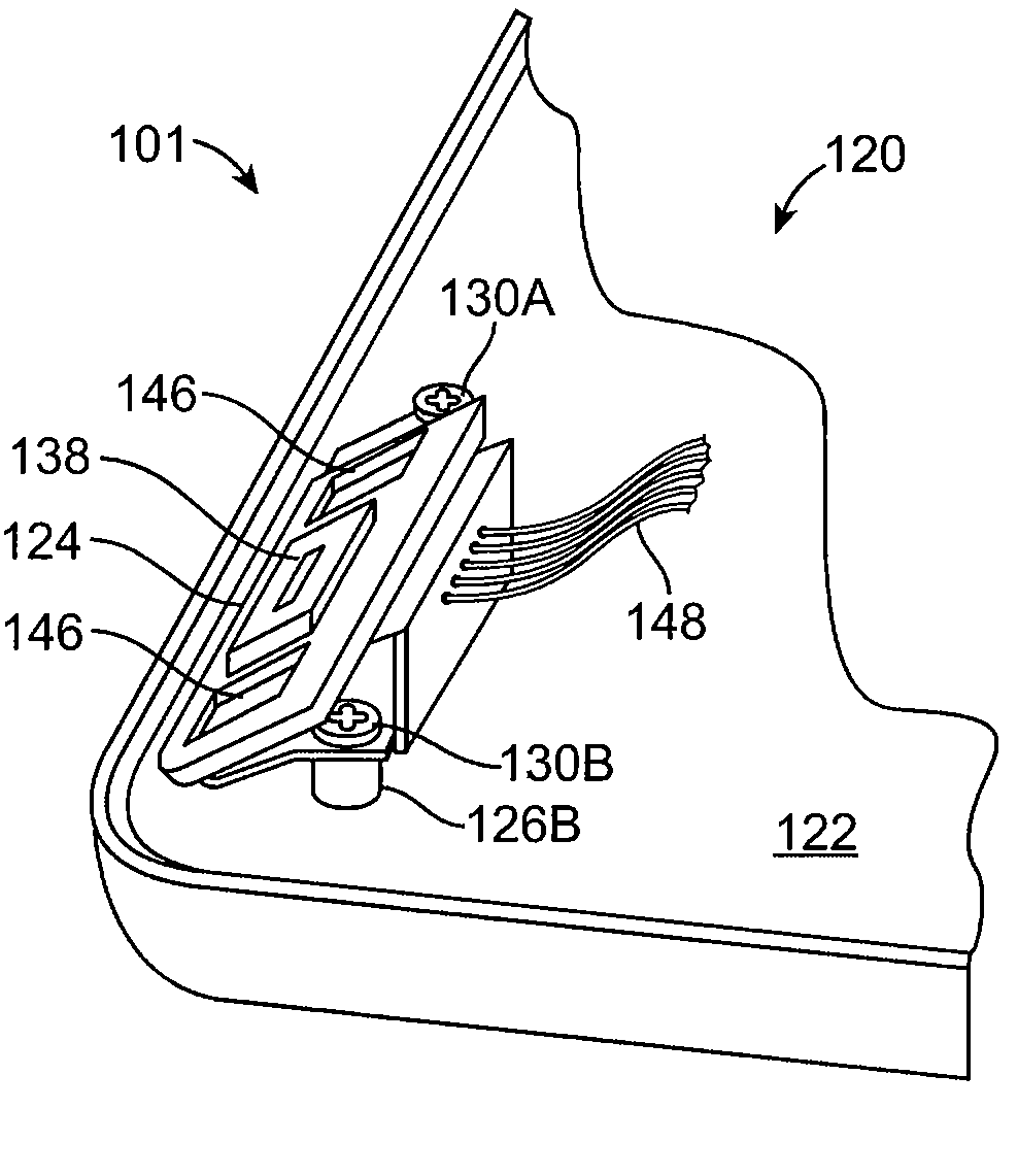
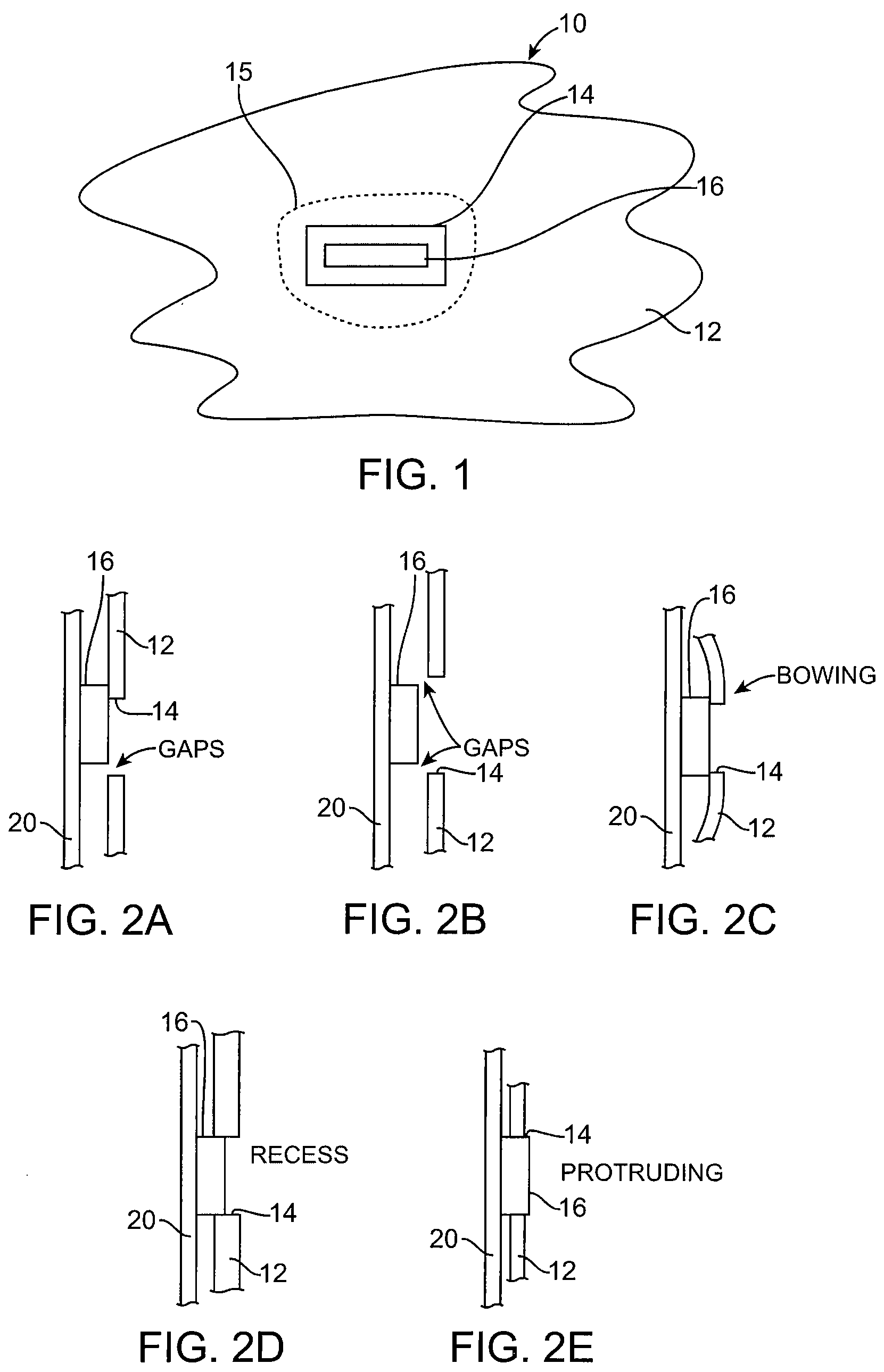
[0040]FIG. 1 is a highly simplified broken away diagram of a portion 10 of an electronic device, in accordance with one embodiment of the present invention. The portion 10 may represent an exterior surface of the electronic device. By way of example, the electronic device may correspond to any consumer electronic product such as computers, phones, media players, and the like.

[0041]As shown, the portion 10 of the electronic device may include a wall 12 with a user accessible I / O region 15. The wall 12 may, for example, be an exterior housing wall of the electronic device, and the I / O region 15 may allow interaction and accessibility between the outside world and the electronic device. Accessibility to the I / O region 15 may include a physical interaction with the electronic device, e.g., a connection or button, and / or a non-contact energy interaction, e.g., visible light detection, infrared light signals. The I / O region 15 may be widely varied. In one embodiment, the I / O region 15 may...


PUM

PropertyMeasurementUnit
magneticaaaaaaaaaa
ferromagneticaaaaaaaaaa
degrees of freedomaaaaaaaaaa

Abstract

An electronic device is disclosed. The electronic device includes a first subassembly having a first housing component. The first housing component has an opening. The electronic device also includes a second subassembly having a second housing component. The second housing component cooperates with the first housing component to enclose components of an electronic device. The at least one internal component is also movable relative to the second subassembly so as to properly align with the opening. The at least one internal component is additionally magnetically attracted towards the first housing component near the opening.

Description

[0001]This application claims the benefit of U.S. Provisional Patent Application No. 61 / 010,116, filed Jan. 4, 2008, and also claims the benefit of U.S. Provisional Patent Application No. 61 / 010,769, filed Jan. 11, 2008, both of which are incorporated herein by reference in their entirety.FIELD OF THE INVENTION[0002]The present invention relates generally to electronic devices. More particularly, the present invention relates to coupling interfacing parts of an electronic device.BACKGROUND OF THE INVENTION[0003]Electronic devices such as portable computers, phones, and media players continue to grow more powerful while shrinking in size and weight. The trend toward smaller, lighter and more powerful electronic devices presents a continuing challenge in the design and manufacture of some components associated with such electronic devices. For example, the design of the enclosures used to house the various internal components of the portable computer is becoming more and more challeng...

Claims


Application Information

Patent Timeline
Patent Type & Authority Patents(United States)
IPC IPC(8): H01R11/30
CPCH01R13/74H05K5/0017Y10T29/49002Y10T29/49947
Inventor LIGTENBERG, CHRISDIFONZO, JOHN C.DEGNER, BRETT WILLIAMBROCK, JOHN
Owner APPLE INC
Why Eureka
Try Eureka