Voltage regulator with current-mode dual-edge pulse width modulation and non-linear control

a voltage regulator and pulse width modulation technology, applied in the field of voltage regulators, can solve the problems of large step change in load current within a relatively short period of time, regulators may not be able to respond fast, and not always the case in real world conditions, and achieve the effect of preventing output voltage overshoo

Active Publication Date: 2010-07-27
SEMICON COMPONENTS IND LLC
View PDF31 Cites 65 Cited by
  • Summary
  • Abstract
  • Description
  • Claims
  • Application Information

AI Technical Summary

Benefits of technology

[0005]In one embodiment, a voltage regulator employs current-mode, dual-edge pulse width modulation and non-linear control. The voltage regulator may include a top switch (e.g., MOSFET) configured to couple a power supply supplying an input voltage to a load. A linear control circuit of the regulator may use a first ramp signal to control turning ON of the top switch and a second ramp signal to control turning OFF of the top switch. The first ramp signal and the second ramp signal are out of phase. A load current detector may detect a step change of load current drawn by the load. When the step change is a step-up change, the non-linear control circuit may turn ON the top switch in between control by the linear control circuit to maintain an output voltage of the regulator within its regulation band. The non-linear control circuit may use the first ramp signal to detect the step-up change. When the step change is a step-down change, the non-linear control circuit may turn OFF the top switch to prevent output voltage overshoot.

Problems solved by technology

However, this is not always the case in real world conditions.
For example, a microprocessor waking out of “sleep” mode may activate a large number of dormant circuits, resulting in a large step change in load current within a relatively short period of time.
In these cases, the regulator may not be able to respond fast enough to maintain the output voltage VOUT within regulation.

Method used


Image

  • Voltage regulator with current-mode dual-edge pulse width modulation and non-linear control
  • Voltage regulator with current-mode dual-edge pulse width modulation and non-linear control
  • Voltage regulator with current-mode dual-edge pulse width modulation and non-linear control

Examples


Embodiment Construction

[0021]In the present disclosure, numerous specific details are provided, such as examples of circuits, components, and methods, to provide a thorough understanding of embodiments of the invention. Persons of ordinary skill in the art will recognize, however, that the invention can be practiced without one or more of the specific details. In other instances, well-known details are not shown or described to avoid obscuring aspects of the invention.

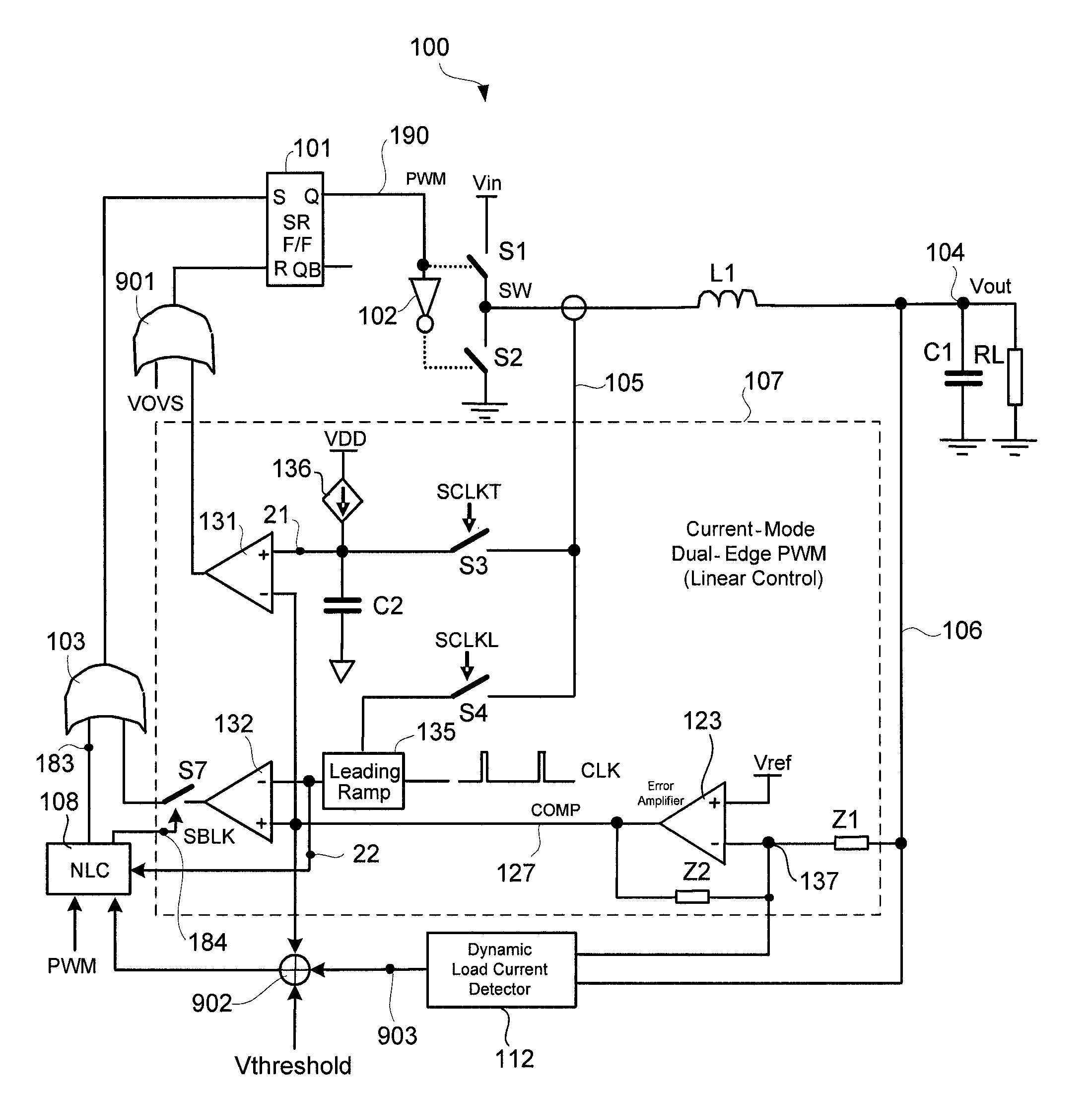
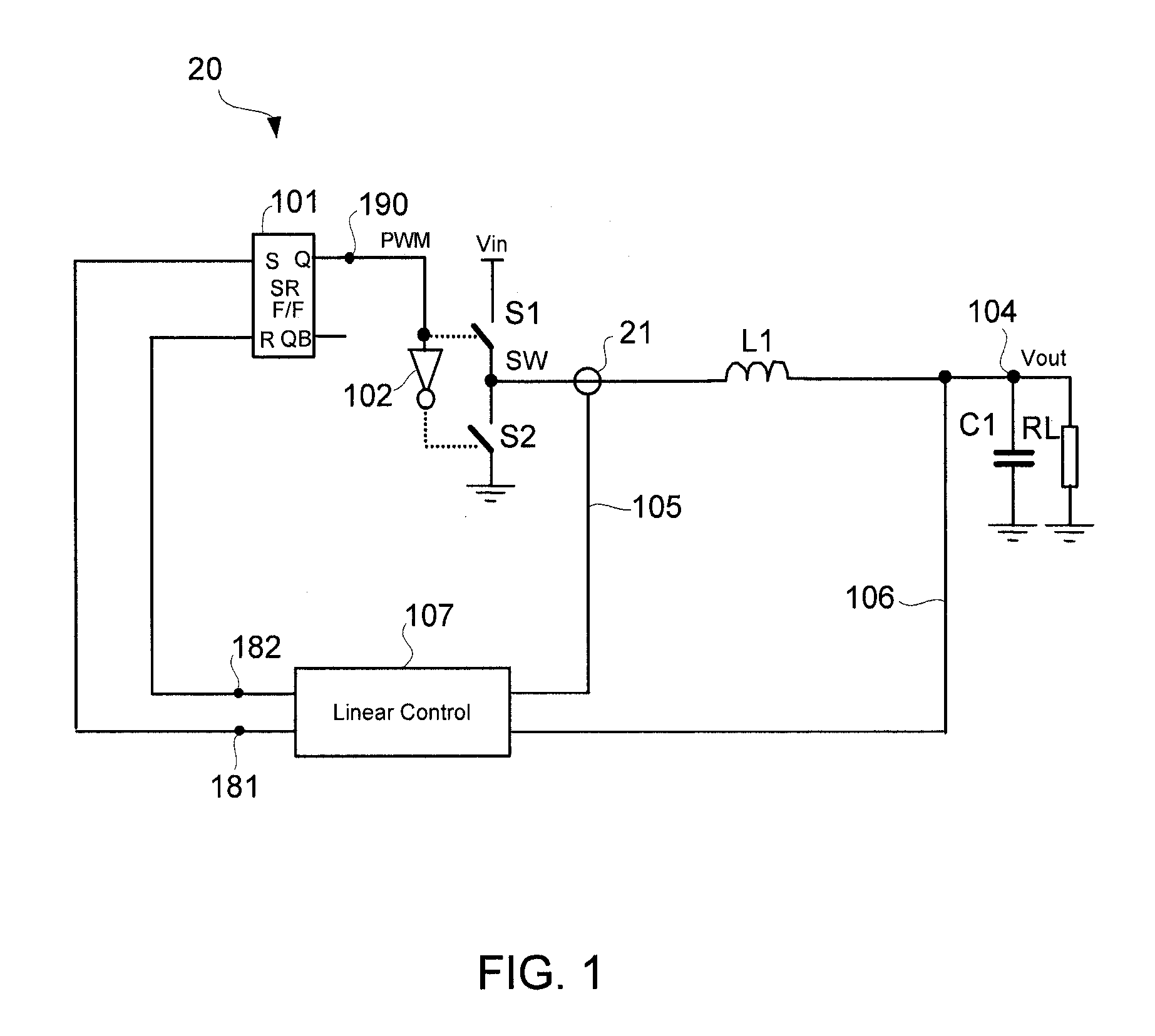
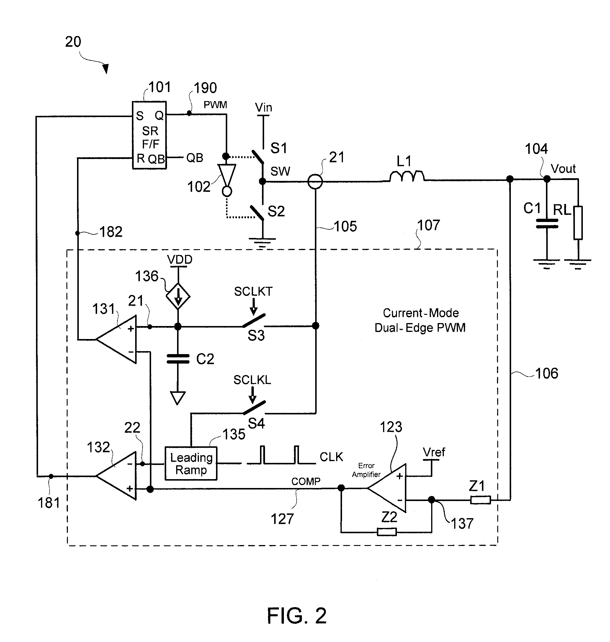
[0022]FIG. 1 schematically shows a voltage regulator 20 in accordance with an embodiment of the present invention. In the example of FIG. 1, the regulator 20 is a buck regulator that takes an input voltage VIN to generate an output voltage VOUT. The regulator 20 may have multiple phases, and thus have several phase output blocks, but only one phase is shown in FIG. 1 for clarity of illustration.

[0023]In one embodiment, the switches S1 and S2 represent synchronously switched transistors (e.g., MOSFET). The switch S1 is also referred to as the...


PUM


Abstract

A voltage regulator with current-mode, dual-edge pulse width modulation (PWM) and non-linear control. The voltage regulator may include a top switch (e.g., MOSFET) configured to couple a power supply supplying an input voltage to a load. A linear control circuit of the regulator may use a first ramp signal to control turning ON of the top switch and a second ramp signal to control turning OFF of the top switch. A non-linear control circuit may turn ON the top switch upon detection of a load current step-up change to maintain an output voltage of the regulator within its regulation band. The non-linear control circuit may turn OFF the top switch upon a load current step-down change to prevent output voltage overshoot.

Description

BACKGROUND OF THE INVENTION[0001]1. Field of the Invention[0002]The present invention relates generally to electrical circuits, and more particularly but not exclusively to voltage regulators.[0003]2. Description of the Background Art[0004]A voltage regulator generates a regulated output voltage VOUT from an input voltage VIN. Ideally, the voltage regulator maintains the output voltage VOUT within regulation despite varying load current. However, this is not always the case in real world conditions. One instance is when the load current is varying at high slew rates and high repetition rates, which may be as much as 1000 A / μs slew rate and up to 1 MHz repetition rate. For example, a microprocessor waking out of “sleep” mode may activate a large number of dormant circuits, resulting in a large step change in load current within a relatively short period of time. As another example, the current drawn by a microprocessor may toggle at high repetition rates when running video games. In ...

Claims


Application Information

Patent Timeline
Patent Type & Authority Patents(United States)
IPC IPC(8): G05F1/16G05F1/00
CPCH02M3/156H02M3/1584
Inventor GUO, YIGANGCAROBOLANTE, FRANCESCO
Owner SEMICON COMPONENTS IND LLC
Why Eureka
Try Eureka