
Digital error signal comparator

Active Publication Date: 2014-05-08
FLEXTRONICS AP LLC
View PDF10 Cites 0 Cited by
  • Summary
  • Abstract
  • Description
  • Claims
  • Application Information

AI Technical Summary

Benefits of technology

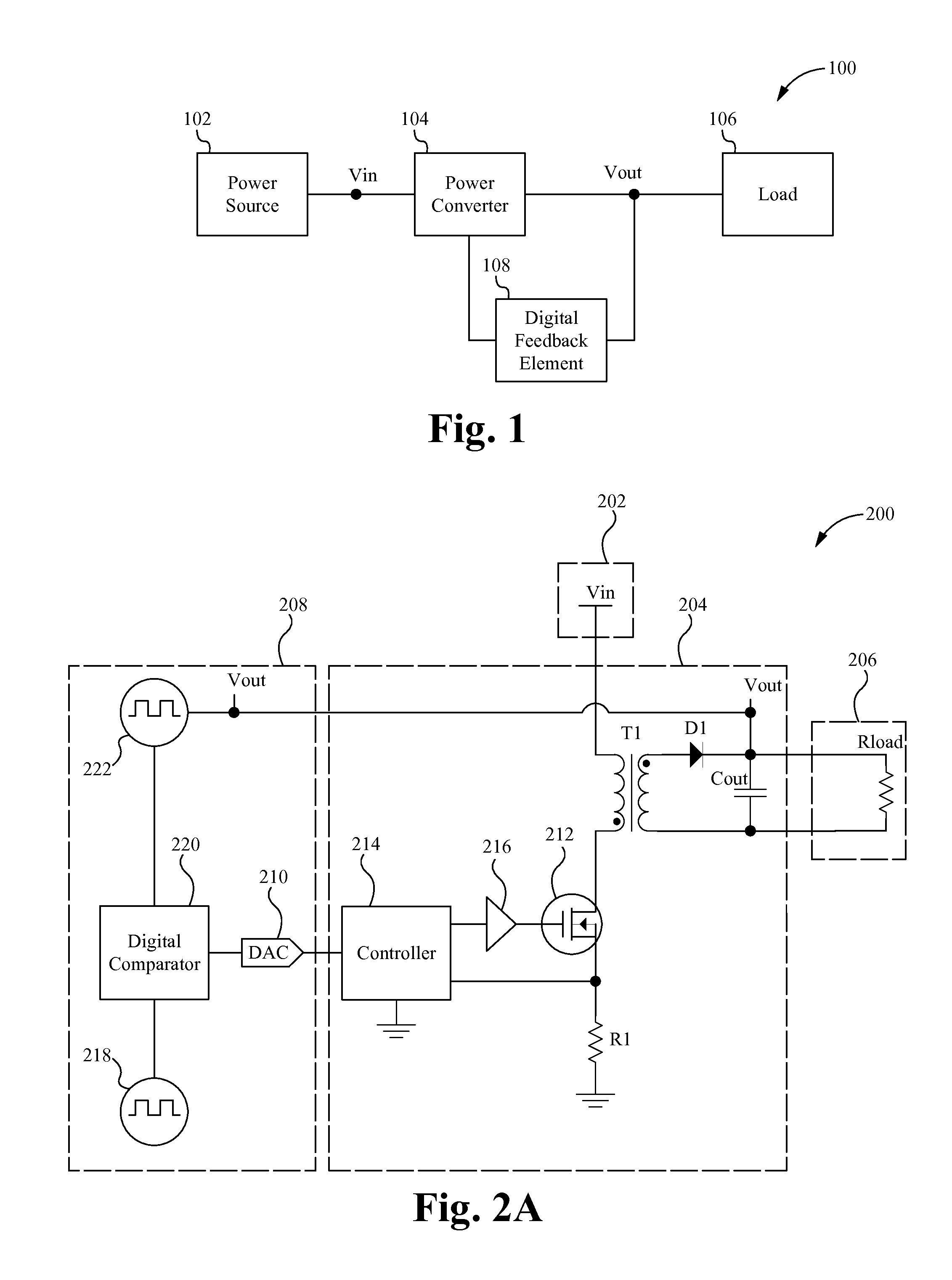
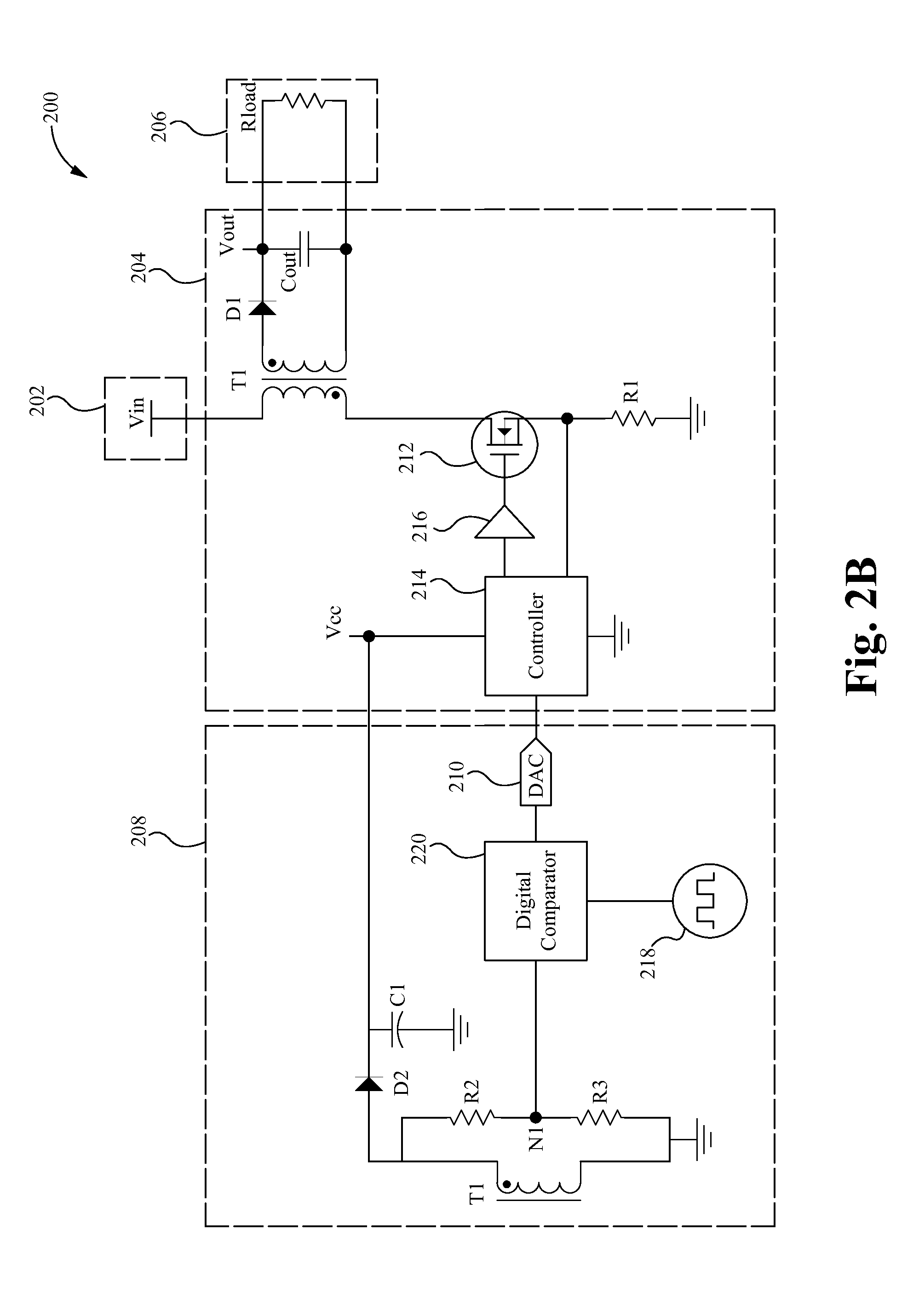
The patent describes a system that uses digital technology to adjust the output voltage of a power converter. This system uses a digital comparator and signal generators to compare a digital signal of the output voltage to a reference signal and determine the amount of error in the output voltage. The system then generates a control signal to compensate for the error and maintain the desired output voltage. This system avoids the need for expensive analog error feedback signals. The technical effect of this patent is to provide a more efficient and cost-effective way to adjust the output voltage of a power converter.

Problems solved by technology

However, these systems result from numerous drawbacks due to their use of analog feedback.
In particular, the analog signals used to transmit the reference and output voltages require temperature, noise, response time and other types of compensation for the systems to operate accurately.
These requirements add cost and limit the capabilities of the power converters.

Method used


Image

  • Digital error signal comparator
  • Digital error signal comparator
  • Digital error signal comparator

Examples


Embodiment Construction

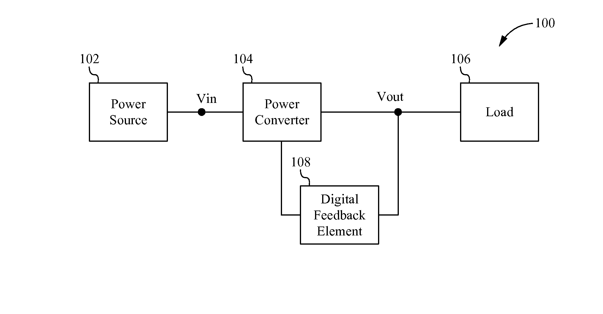
[0011]In the following description, numerous details and alternatives are set forth for the purpose of explanation. However, one of ordinary skill in the art will realize that the invention can be practiced without the use of these specific details. In other instances, well-known structures and devices are shown in block diagram form in order not to obscure the description of the invention with unnecessary detail. In particular, it should be noted that although the digital error feedback system, device and method is described herein in reference to input, output and reference voltages, it is understood that the system, device and method are able to similarly operate in reference to input, output and reference currents and / or voltages.

[0012]Embodiments of a digital error feedback system, method and device for adjusting the output voltage of a power converter are described herein. The digital error feedback system uses a digital comparator and one or more digital signal generators to ...


PUM


Abstract

A digital error feedback system, method and device adjusts the output voltage of a power converter. The digital error feedback system uses a digital comparator and one or more digital signal generators to generate and compare a digital signal corresponding to the output voltage to a reference digital signal in order to determine the current amount of error in the output voltage. The error is then able to be compensated for using a control signal generated based on the determined error.

Description

FIELD OF THE INVENTION[0001]The present invention relates to the field of power supplies. More particularly, the present invention relates to a power converter system with a digital error feedback feature.BACKGROUND[0002]Power converters are devices that receive power from a power source and converter that power into an output power that is suitable for powering a load that is coupled to the power converter. To maintain a stable output power, conventional power converters include analog feedback components. These analog components measure the output voltage on the load and compare that voltage to a controlled reference voltage that is known to be at the desired voltage to determine the error or how different the actual output voltage is from the desired output voltage. The analog components then utilize this determined error to adjust the operation of the power converter to compensate for the measured error. However, these systems result from numerous drawbacks due to their use of a...

Claims


Application Information

Patent Timeline
IPC IPC(8): G05F1/10
CPCH02M3/33515H02M3/33523
Inventor TELEFUS, JR., MARK
Owner FLEXTRONICS AP LLC
Learn More