
Inductive coupled power supply and slope control

a power supply and coupled technology, applied in the direction of power conversion systems, dc-dc conversion, instruments, etc., can solve the problems of large circuit components, and limited ability of conventional switching power supplies to maintain output voltag

Active Publication Date: 2021-11-02
INFINEON TECH AUSTRIA AG
View PDF17 Cites 0 Cited by
  • Summary
  • Abstract
  • Description
  • Claims
  • Application Information

AI Technical Summary

Benefits of technology

Enables better response to transient load conditions by dynamically adjusting current flow, maintaining output voltage regulation during sudden changes in load current without significant increases in component size or efficiency loss.

Problems solved by technology

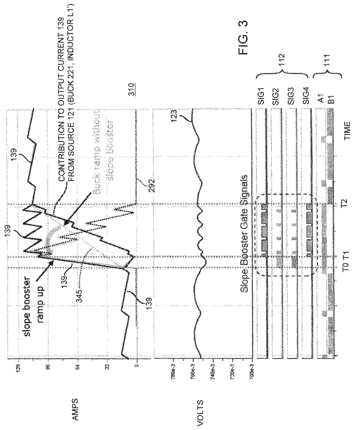
This disclosure includes the observation that conventional switching power supplies have a limited ability to maintain an output voltage within a desired range during transient load conditions.
For example, conventional switching power supplies are limited as to how quickly they are able to switch from outputting 1 Amp (Amperes) to outputting 100 Amps (and vice versa).
However, such modifications can require a larger sized circuit components and reduce circuit efficiency of a respective power supply.

Method used


Image

  • Inductive coupled power supply and slope control
  • Inductive coupled power supply and slope control
  • Inductive coupled power supply and slope control

Examples


Embodiment Construction

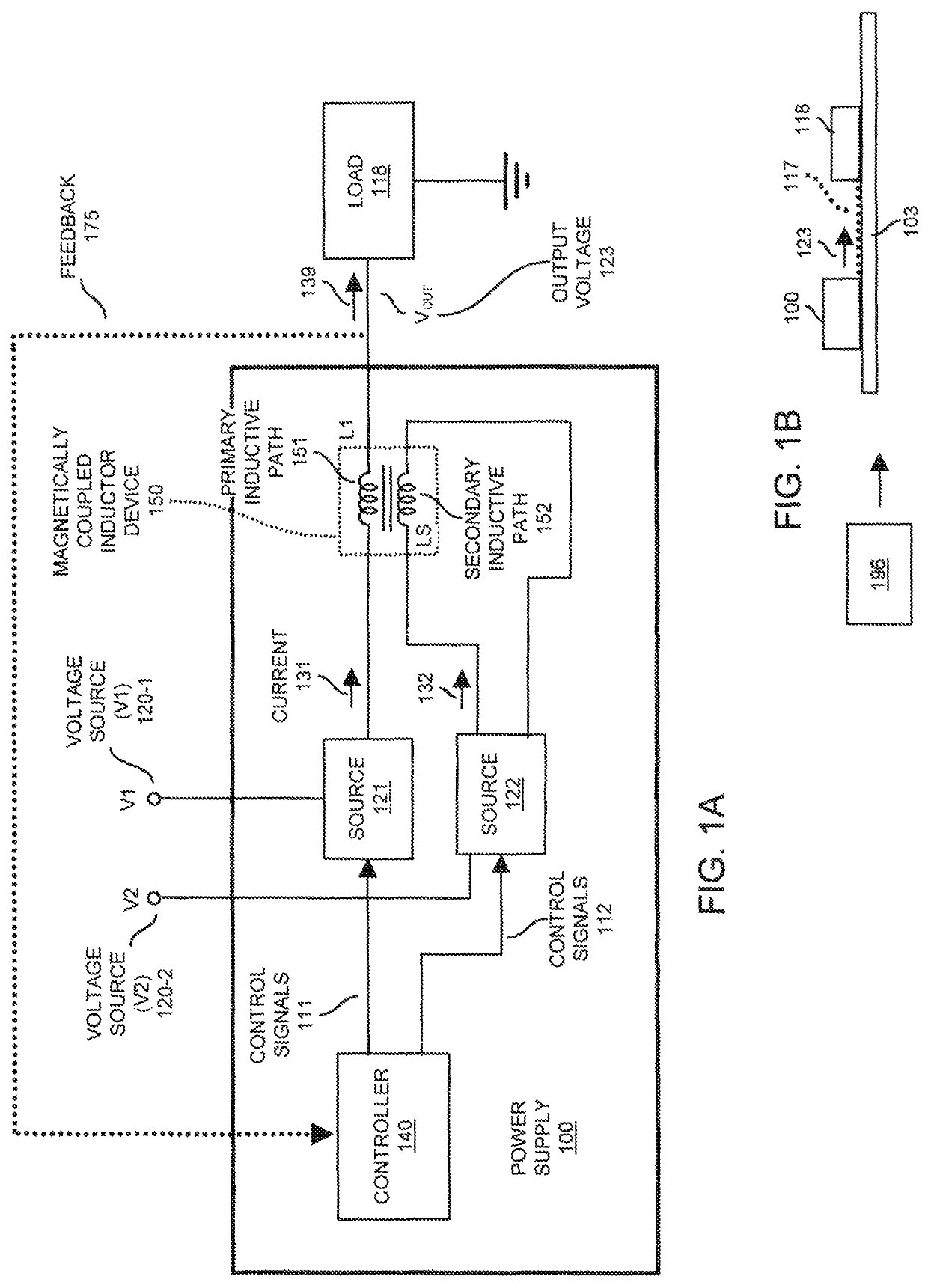
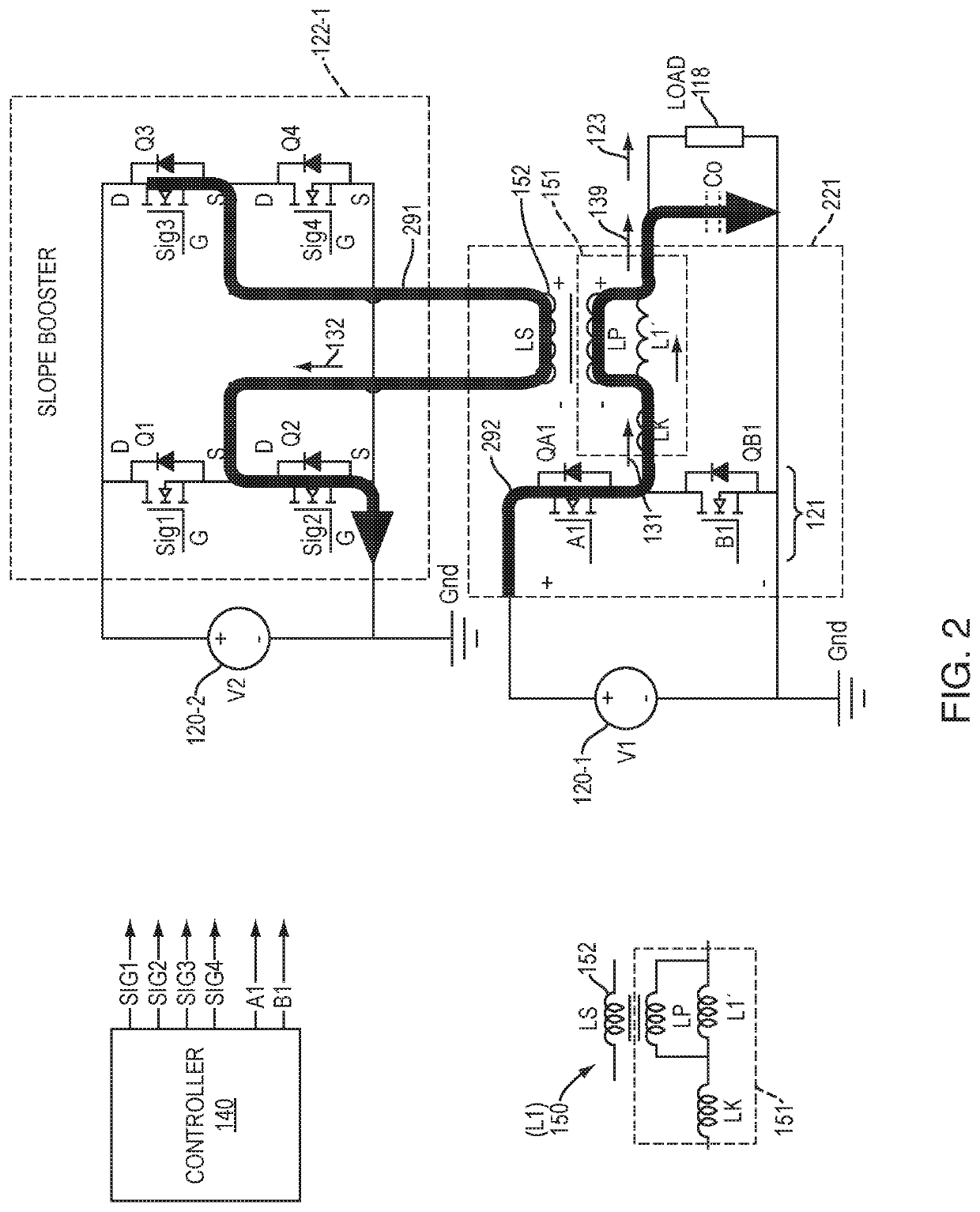
[0051]A power supply includes a power source, a primary inductive path, and a secondary inductive path. The primary inductive path is coupled to receive input current from the power source. The secondary inductive path is magnetically coupled to the primary inductive path to adjust current flow through the primary inductive path, the primary inductive path operative to produce an output voltage.

[0052]Now, with reference to the drawings, FIG. 1A is an example diagram illustrating a power supply including a primary inductive path and a secondary inductive path according to embodiments herein.

[0053]In this example embodiment, the power supply 100 produces output voltage 123 that powers the dynamic load 118 (such as one or more electronic circuits, components, etc.).

[0054]The power supply 100 includes multiple components such as a controller 140, source 121 (such as a current source, voltage source, power source, etc.), source 122 (such as current source, voltage source, power source, e...


PUM


Abstract

A power supply includes a power source, a primary inductive path, and a secondary inductive path. The primary inductive path coupled to receive input current from the power source. The secondary inductive path is magnetically coupled to the primary inductive path to adjust current flow through the primary inductive path, the primary inductive path operable to produce an output voltage.

Description

BACKGROUND[0001]Conventional switching power supply circuits sometimes include an energy storage component such as an inductor to produce an output voltage that powers a load. For example, to maintain a magnitude of an output voltage within a desired range, a controller controls switching of input current through the inductor.[0002]A drawback of the inductor-based power supply is the ability to input sufficient current into the inductor during changing load conditions (such as when the load instantaneously consumes more or less power) so that the output voltage stays within regulation.[0003]For example, a load may operate in a steady state condition in which the load consumes a current of 10 Amperes in steady state and then suddenly switches over to consuming a much greater current of 100 Amperes. Conversely, the load may operate in a steady state condition in which the load consumes 100 Amperes in steady state and then suddenly switches over to consuming much less current of 10 Amp...

Claims


Application Information

Patent Timeline
Patent Type & Authority Patents(United States)
IPC IPC(8): H02M3/156H02M3/157H02M3/158
CPCH02M3/158H02M3/1566H02M3/33573H02M1/0064
Inventor LEONG, KENNITH K.KASPER, MATTHIAS J.PELUSO, LUCADEBOY, GERALD
Owner INFINEON TECH AUSTRIA AG
Learn More