Switching between layer 2 switches as destination of IP packets from cards

a technology of switching between layer 2 switches and ip packets, applied in data switching networks, frequency-division multiplexes, instruments, etc., can solve problems such as packet loss, process is subject to the danger of a duplication of ip packets, and ip networks are not supposed to guarantee a sequence of ip packets, so as to reduce costs and simplify arrangement

Inactive Publication Date: 2010-07-27
NEC CORP
View PDF19 Cites 7 Cited by
  • Summary
  • Abstract
  • Description
  • Claims
  • Application Information

AI Technical Summary

Benefits of technology

[0011]Another object of the present invention is to provide a layer 2 switch switching circuit, a base station apparatus, and a layer 2 switch switching method which are capable of preventing a packet loss, a duplication, and a scrambled sequence of IP packets when a destination of IP packets is switched from a layer 2 switch to another layer 2 switch.
[0017]With this arrangement, even when each of the layer 2 switches detects when the companion layer 2 switch changes from the active state to the standby state, it waits until the transmission of all the IP packets held by the internal buffer of the companion layer 2 switch is completed. Therefore, it is possible to prevent a packet loss from occurring which would be caused if past IP packets remain in the companion layer 2 switch. As a packet loss is prevented from occurring, it is not necessary to send at all times replicas of IP packets from the layer 2 switch from which the destination of IP packets is to be switched to the layer 2 switch to which the destination of IP packets is to be switched, and hence a duplication of IP packets is avoided. Furthermore, because each of the layer 2 switches resumes sending IP packets after the transmission of all the IP packets held by the internal buffer of the companion layer 2 switch is completed, the sequence of IP packets sent to cards is prevented from being scrambled.
[0019]With this arrangement, each of the cards is capable of sending IP packets to the layer 2 switches even while the destination of IP packets is being changed. Inasmuch as there is no need to hold IP packets in each of the cards, each of the cards may be simplified in arrangement, and may be manufactured at a reduced cost.

Problems solved by technology

When the destination of IP packets is switched from a layer 2 switch to another layer 2 switch, IP packets in the past remain held in the layer 2 switch which was active prior to the switching, tending to result in a packet loss.
However, this process is subject to the danger of a duplication of IP packets during the switching.
Generally, IP networks are not supposed to guarantee a sequence of IP packets.
However, if a sequence of IP packets is not guaranteed, then a receiver of the IP packets needs to perform some process of correcting the sequence in which the IP packets are received.

Method used


Image

  • Switching between layer 2 switches as destination of IP packets from cards
  • Switching between layer 2 switches as destination of IP packets from cards
  • Switching between layer 2 switches as destination of IP packets from cards

Examples


Embodiment Construction

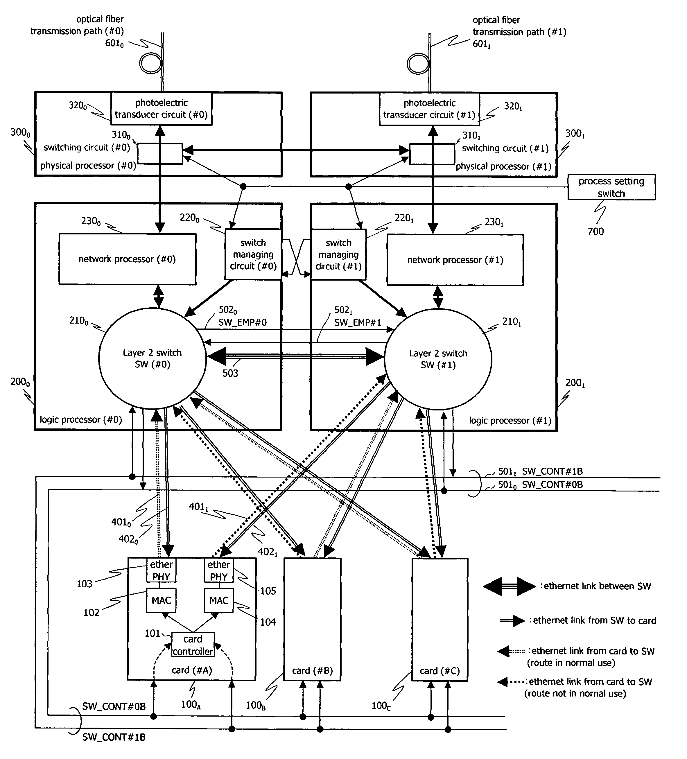
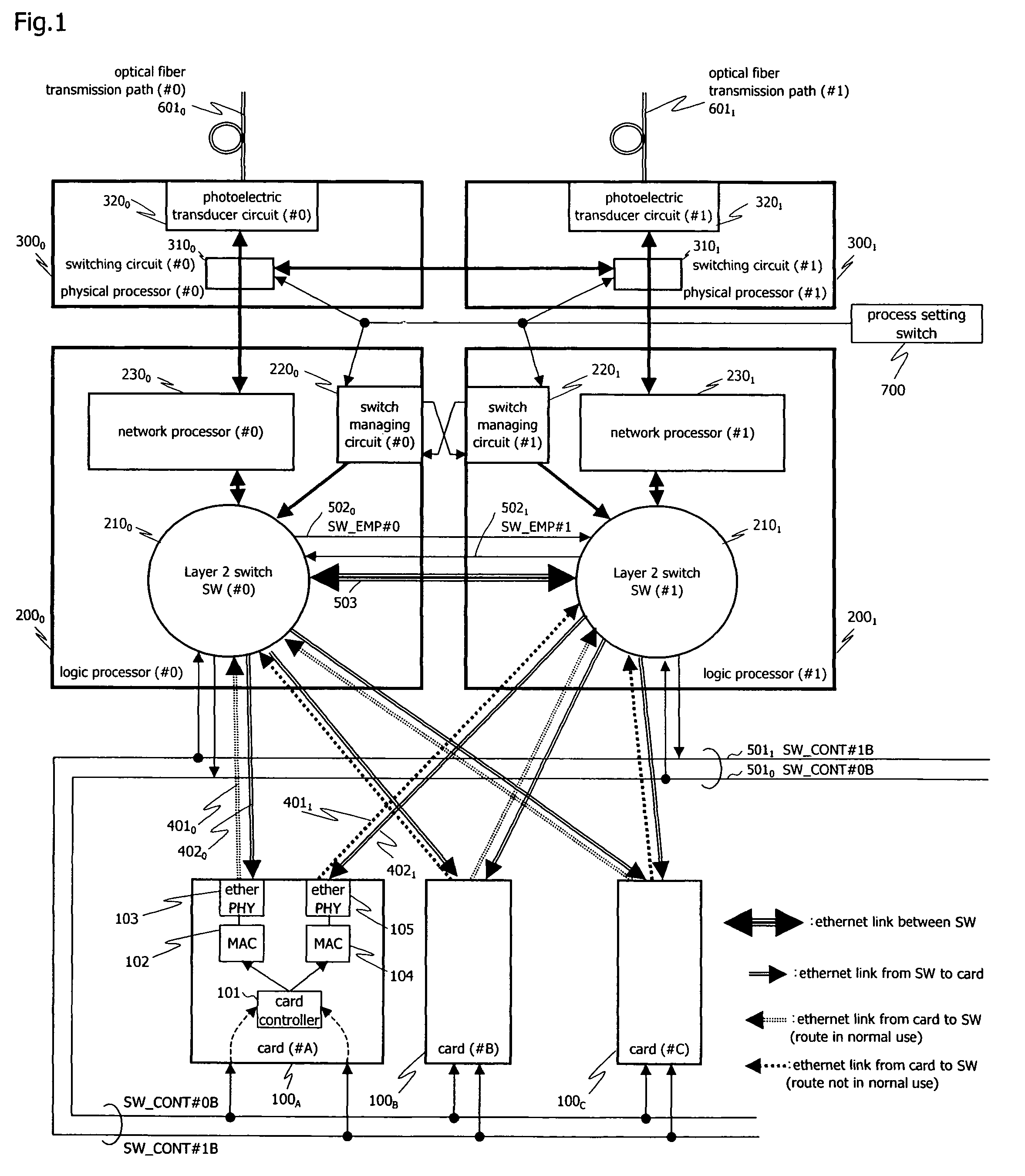
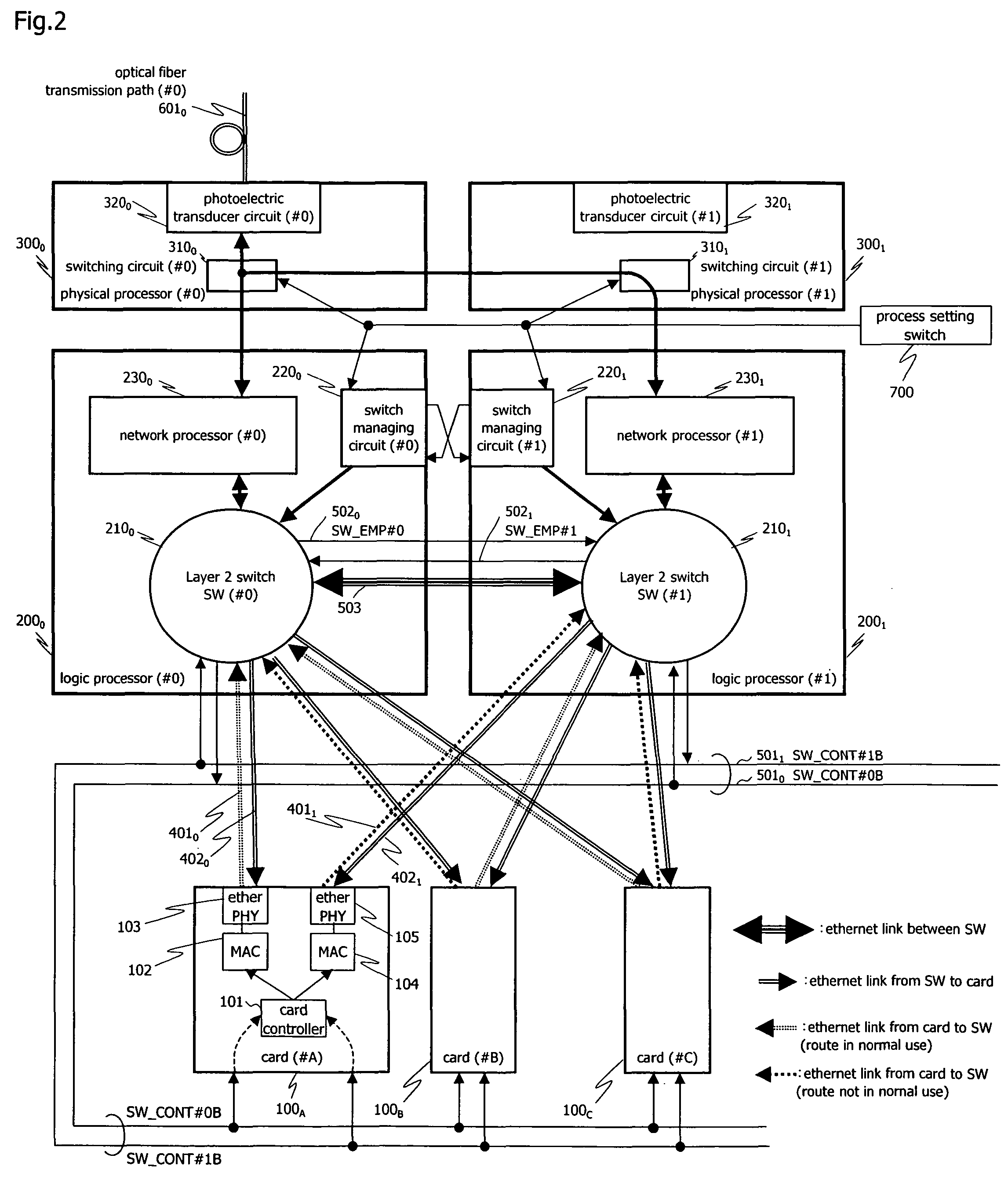
[0028]A layer 2 switch switching circuit according to an embodiment of the present invention is illustrated in FIGS. 1 and 2. The layer 2 switch switching circuit illustrated in FIG. 1 and the layer 2 switch switching circuit illustrated in FIG. 2 are identical in structure with each other. However, FIG. 1 shows the layer 2 switch switching circuit as it is incorporated in a dual active system, and FIG. 2 shows the layer 2 switch switching circuit as it is incorporated in an active-backup system.

[0029]As shown in FIGS. 1 and 2, the layer 2 switch switching circuit according to the embodiment of the present invention has a plurality of cards (#A through #C) 100A through 100C, logic processor (#0) 2000 and physical processor (#0) 3000 belonging to system 0, logic processor (#1) 2001 and physical processor (#1) 3001 belonging to system 1, and process setting switch 700. The layer 2 switch switching circuit is installed in a wireless or wired base station apparatus.

[0030]Though only thr...


PUM


Abstract

A layer 2 switch switching circuit has two layer 2 switches of a redundant configuration and a plurality of cards for sending IP packets to each other through either one of the two layer 2 switches. Each of the two layer 2 switches has a state signal delivery unit for delivering a state signal representing whether the layer 2 switch is in an active state or a standby state. Each of the cards has a card controller for monitoring states of the two layer 2 switches based on state signals sent respectively from the two layer 2 switches, and switching between the two layer 2 switches as a destination of IP packets based on the monitored states.

Description

BACKGROUND OF THE INVENTION[0001]1. Field of the Invention[0002]The present invention relates to a technology for switching between two layer 2 switches as a destination of IP packets from a plurality of cards of a base station apparatus which transmit IP packets through either one of the two layer 2 switches. A layer 2 switch refers to a switch for delivering an IP packet depending on the data of the IP packet in a layer 2 (data link layer).[0003]2. Description of the Related Art[0004]Generally, redundant configurations include a dual active system configuration having two systems both used as active systems and an active-backup system configuration having two systems used as an active system and a backup system, respectively. Active-backup system configurations are disclosed in JP-A-1999-246646, JP-A-1993-344144, JP-A-1997-135244, and JP-A-2003-234757 (hereinafter referred to as Documents 1 through 4, respectively).[0005]Dual active and active-backup schemes need to be used differ...

Claims


Application Information

Patent Timeline
Patent Type & Authority Patents(United States)
IPC IPC(8): H04L12/66H04L12/28H04L45/586
CPCH04L43/0817H04L43/16
Inventor MURAI, MASAO
Owner NEC CORP
Why Eureka
Try Eureka