Fixing device and image forming apparatus

a technology of fixing device and image forming apparatus, which is applied in the direction of electrographic process apparatus, instruments, optics, etc., can solve the problems of lowering image quality, etc., and achieve stable pressing, preventing distortion, shift, or irregularity in images, the effect of improving image quality

Active Publication Date: 2010-07-27
OKI ELECTRIC IND CO LTD
View PDF6 Cites 8 Cited by
  • Summary
  • Abstract
  • Description
  • Claims
  • Application Information

AI Technical Summary

Benefits of technology

[0011]In particular, the supporting shaft supports the supporting member to be freely rotatable, and the supporting member supports the pressing member. Further, the urging member urges the supporting member in the specific rotational direction, and urges the pressing member against the heating member. Accordingly, the pressing member is not inclined, or does not vibrate or wobble, so that the pressing member does not seize other component. As a result, it is possible to stably press the pressing member against the heating member, thereby preventing distortion, shift, or irregularity in an image, and improving image quality.

Problems solved by technology

As a result, it is difficult to stably press the pressing pad 106 against the fixing roller 103, thereby causing distortion, shift, or irregularity in an image, and lowering image quality.

Method used


Image

  • Fixing device and image forming apparatus
  • Fixing device and image forming apparatus
  • Fixing device and image forming apparatus

Examples


first embodiment

[0025]A first embodiment of the present invention will be explained. FIG. 3 is a schematic sectional view showing a printer according to the first embodiment of the present invention.

[0026]As shown in FIG. 3, the printer includes a sheet supply cassette 11 as a recording medium storage unit disposed at a lower portion of the printer for storing a sheet (not shown) as a recording medium. A sheet supply mechanism is disposed adjacent to a front end of the sheet supply cassette 11 for separating and transporting the sheet one by one. The sheet supply mechanism includes sheet supply rollers 12a and 12b and a separation roller 13.

[0027]In the embodiment, the sheet supply mechanism transports the sheet to a transport roller 14 disposed above the sheet supply mechanism, and then transports the sheet further to a transport roller 15. Afterward, a transport belt 17 as a transport member or a first transfer member moves and transports the sheet, so that the sheet passes through between image ...

second embodiment

[0070]A second embodiment of the present invention will be explained next. Components in the second embodiment similar to those in the first embodiment are designated with the same reference numerals, and explanations thereof are omitted. The components similar to those in the first embodiment provide the similar effects.

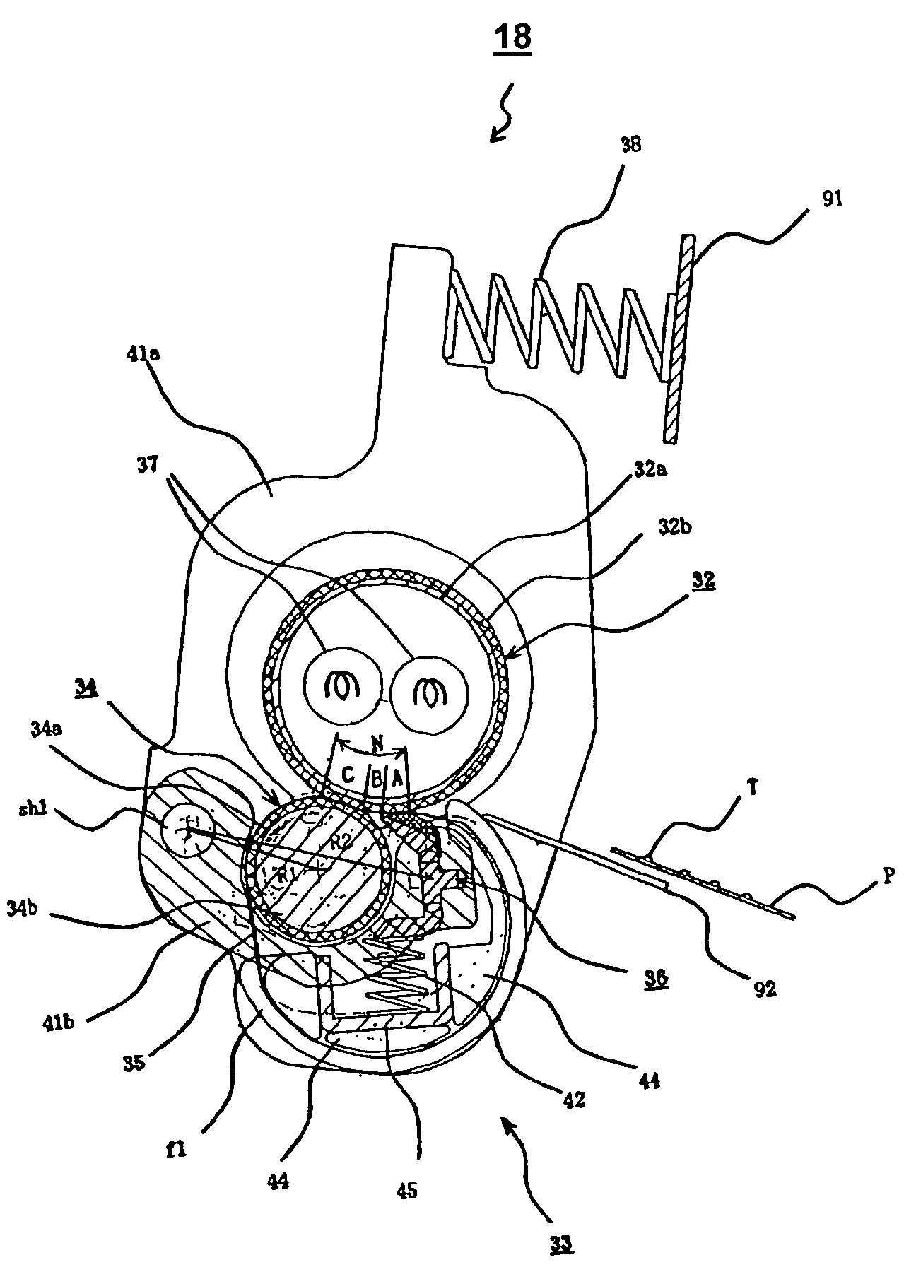
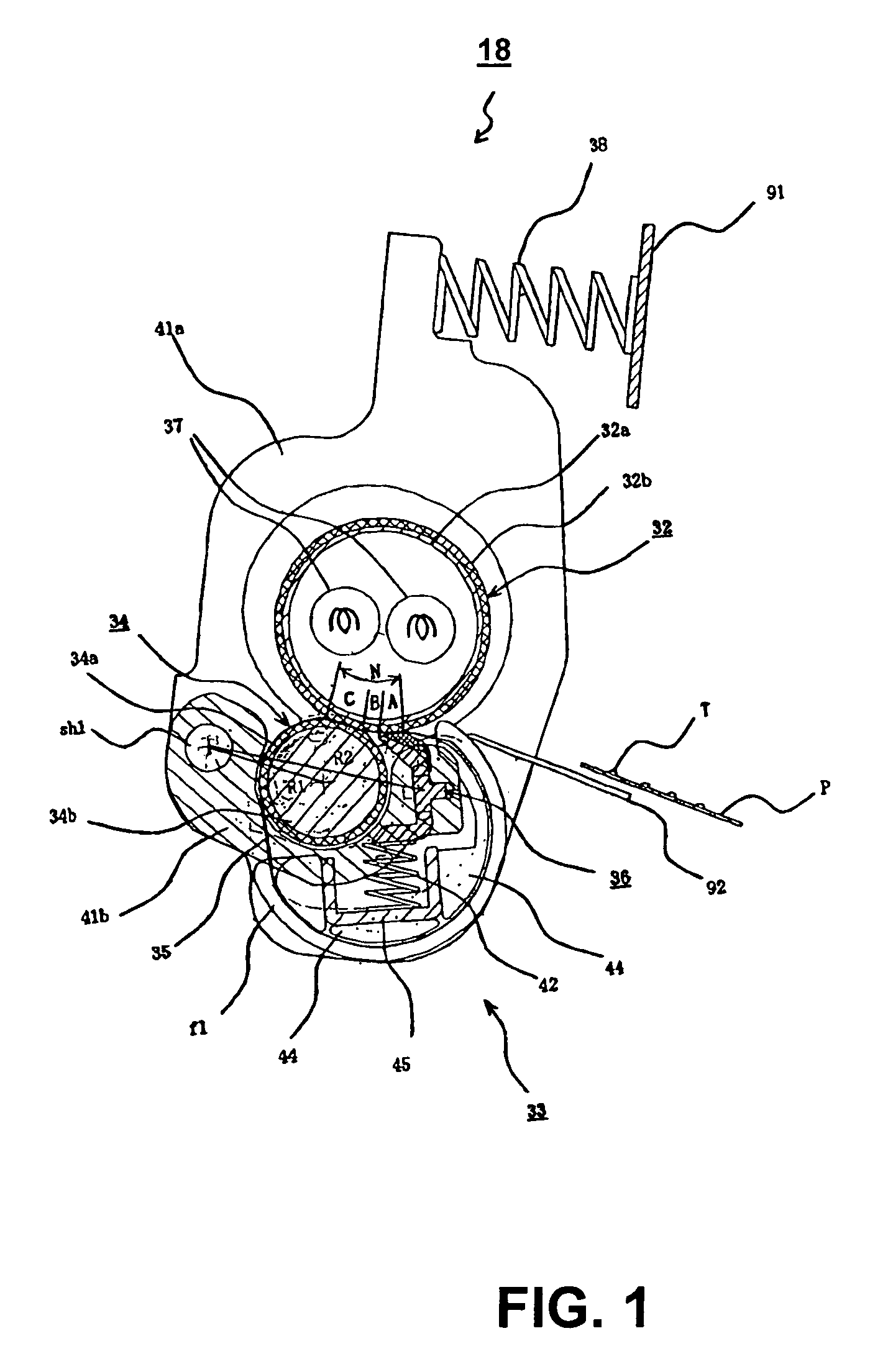
[0071]FIG. 10 is a schematic sectional view showing a fixing device according to the second embodiment of the present invention. FIG. 11 is a perspective view showing a primary portion of the fixing device according to the second embodiment of the present invention. FIG. 12 is an exploded perspective view showing the primary portion of the fixing device according to the second embodiment of the present invention.

[0072]As shown in FIGS. 11 and 12, the both end portions of the pressing roller 34 as the pushing member are supported on pressing roller levers 61a disposed at left and right sides as a first supporting member through the bearings br1, so that the pressing ...


PUM


Abstract

A fixing device includes a heating member for heating a recording medium having a developer image; a pressing member for pressing the recording medium against the heating member; a supporting member for supporting the pressing member; a supporting shaft for supporting the supporting member to be freely rotatable; and an urging member for urging the supporting member in a specific rotational direction and urging the pressing member against the heating member.

Description

BACKGROUND OF THE INVENTION AND RELATED ART STATEMENT[0001]The present invention relates to a fixing device and an image forming apparatus.[0002]In a conventional image forming apparatus such as a printer, a copier, and a facsimile, an image is formed through the following process. First, a charge roller charges a surface of a photosensitive drum. An exposure device such as an LED head exposes the surface of the photosensitive drum to form a static latent image or a latent image thereon. A developing roller attaches a thin layer of toner to the static latent image to form a toner image. A transfer roller transfers the toner image to a sheet. A fixing unit or fixing device fixes the toner image to the sheet before discharging the sheet.[0003]Patent Reference has disclosed a conventional fixing device of a belt nip type. The conventional fixing device is provided with a pressing pad pressed against a fixing roller or a fixing member through a pressing belt.[0004]FIG. 2 is a schematic ...

Claims


Application Information

Patent Timeline
Patent Type & Authority Patents(United States)
IPC IPC(8): G03G15/20
CPCG03G15/206G03G2215/2009
Inventor TSUNODA, SHIGERU
Owner OKI ELECTRIC IND CO LTD
Why Eureka
Try Eureka