Ventilating spacing strip between rear surface of siding and outer surface of structure allowing horizontal air circulation

a technology of ventilation spacing and siding, which is applied in the direction of walls, ceilings, roofing, etc., can solve the problems of restricted horizontal cross ventilation, visible bows in the siding about vertical axes between those nailed portions, and visible bows in the siding about horizontal axes, so as to facilitate manual engagement with the spacer and facilitate the effect of inserting the spacer

Inactive Publication Date: 2010-08-03
FINN SYST
View PDF33 Cites 21 Cited by
  • Summary
  • Abstract
  • Description
  • Claims
  • Application Information

AI Technical Summary

Benefits of technology

[0007]The present invention provides specially shaped spacers and a method for using such spacers between an underlying structure on the outside wall of a building and each of the portions of lengths of lap siding through which the lengths of siding are nailed to the underlying structure to provide a ventilation space between the rear surfaces of the lengths of siding and the underlying structure while restricting visible bowing the lengths of siding; and also provides a building comprising an outside wall that can be made by that method and which can include novel means for opening the ventilation space to the atmosphere at its upper and lower ends.
[0009]The spacers each include a projecting portion having a stop surface at and projecting above the first or upper edge of the second plane defined by the support surface or support surfaces. The projecting portion can facilitate manual engagement with the spacer while the spacer is positioned behind a length of siding or inserted between a length of siding and the underlying structure, and helps locate the spacer or stops such insertion when the stop surface contacts the upper edge of the length of siding. The projecting portion extends from the stop surface to a top end of the spacer and projects above the first or upper edge of the plane defined by the support surface or support surface portions a distance (e.g., 5 / 16 inch or 0.79 cm) about equal to or less than the thickness of the lengths of siding along their upper edges.
[0010]The spacers can also each include a tapered portion extending from the second or lower edge of the second plane defined by the support surface or support surfaces to a bottom end of the spacer, which tapered portion has a front wedge surface or wedge surfaces on the side of the spacer opposite the rear surface or rear surfaces and disposed generally in and defining a third plane that converges away from that second edge toward the first plane defined by the rear surface or rear surfaces at an acute angle (e.g., about 20 degrees) between the first and third planes. The tapered portion provides a wedge which can facilitate inserting the spacer between the rear surface of a length of siding and the outer surface of the underlying structure.
[0012]The spacers can have lengths between their top and bottom ends that are significantly less (e.g., preferably no more that about ½) the widths of the lengths of siding with which they are used so that there is a space between vertically aligned spacers used to attach the lengths of siding. Thus the ventilation space provided by the spacers between the underlying structure and the lengths of siding can afford movement of air and moisture in both horizontal and vertical directions in the ventilation space.
[0014]The spacer can have a continuous front support surface that provides support centrally across the second plane defined by its support surface or surfaces so that it provides support for the rear surface of a length of siding around a fastener (e.g., a nail) as that fastener is driven through that length of siding, the spacer, and into the underlying structure. Such support for the rear surface of the length of siding restricts portions of the siding around that fastener along the rear surface of the siding from being broken out by movement of the fastener through the length of siding. Alternatively, if the material from which the length of siding is made does not need such support, the spacer can have a passageway that extends through the center of the second plane defined by the support surface or support surfaces through which passageway that fastener can pass so that the spacer causes little or no increase in the force needed to insert that fastener through the length of siding and spacer and into the underlying structure compared to fastening the length of siding to the underlying structure without the spacer.

Problems solved by technology

That ventilation space is only provided between the vertical strips so that horizontal cross ventilation is restricted.
Also, nailing the lap siding to those strips can cause visible bows about horizontal axes in the lengths of siding between their upper portions that are nailed to the strips and their lower portions that extend over the upper portions of the lengths of siding below them.
Also, nailing the lengths of siding to the underlying structure through the corrugated sheet can collapse the corrugations in the sheet under the nailed portions of the siding, whereas the portions of the siding between the nailed portions are held away from the underlayment by the corrugated sheet, thereby causing visible bows in the siding about vertical axes between those nailed portions.

Method used


Image

  • Ventilating spacing strip between rear surface of siding and outer surface of structure allowing horizontal air circulation
  • Ventilating spacing strip between rear surface of siding and outer surface of structure allowing horizontal air circulation
  • Ventilating spacing strip between rear surface of siding and outer surface of structure allowing horizontal air circulation

Examples


Embodiment Construction

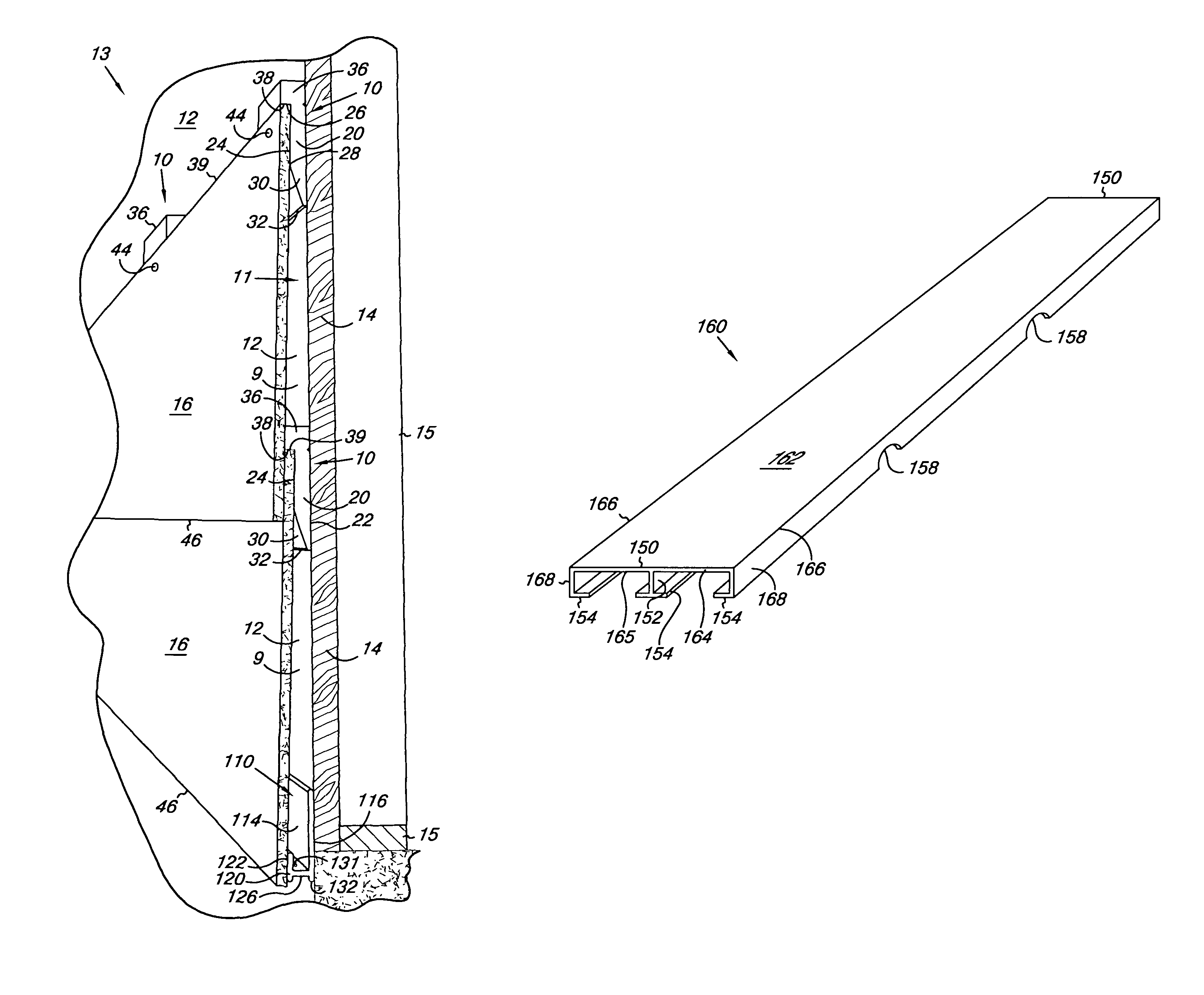
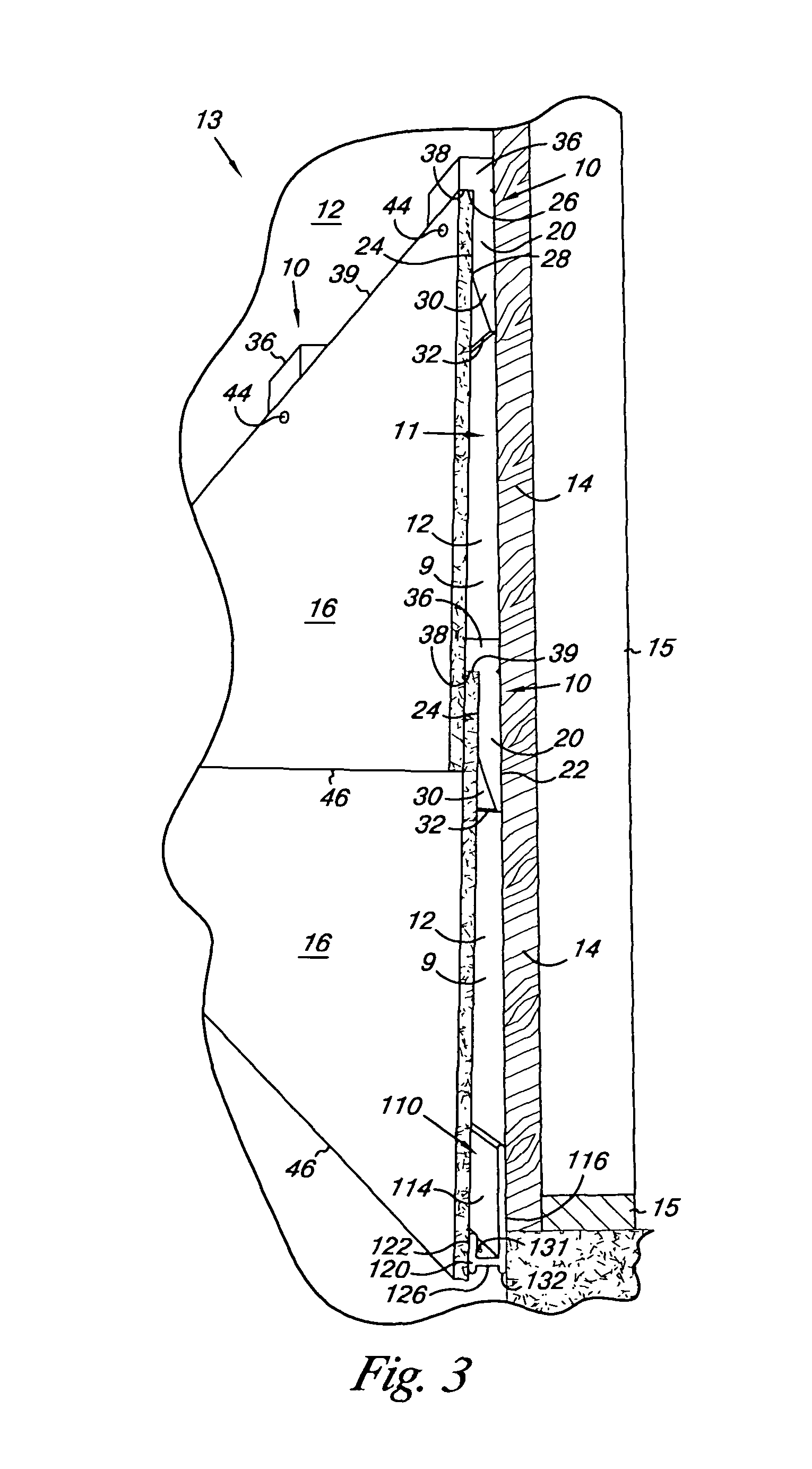
[0034]With reference to FIGS. 1, 2, 3, 4, and 4a of the drawing, the present invention comprises specially shaped spacers 10 adapted to be used between a generally planar vertical outer surface on an underlying structure 11 of an outer sidewall of a building 13 and each of the portions of lengths of siding 16, through which spacers 10 the lengths of siding 16 are fastened to the underlying structure 11 to provide a ventilation space 9 between the inner or rear surfaces of the lengths of siding 16 and the vertical outer surface of the underlying structure 11. Use of the spacers 10 to provide that ventilation space 9 can afford movement of air in any direction in that ventilation space 9 and can restrict visible bowing of the lengths of siding 16.

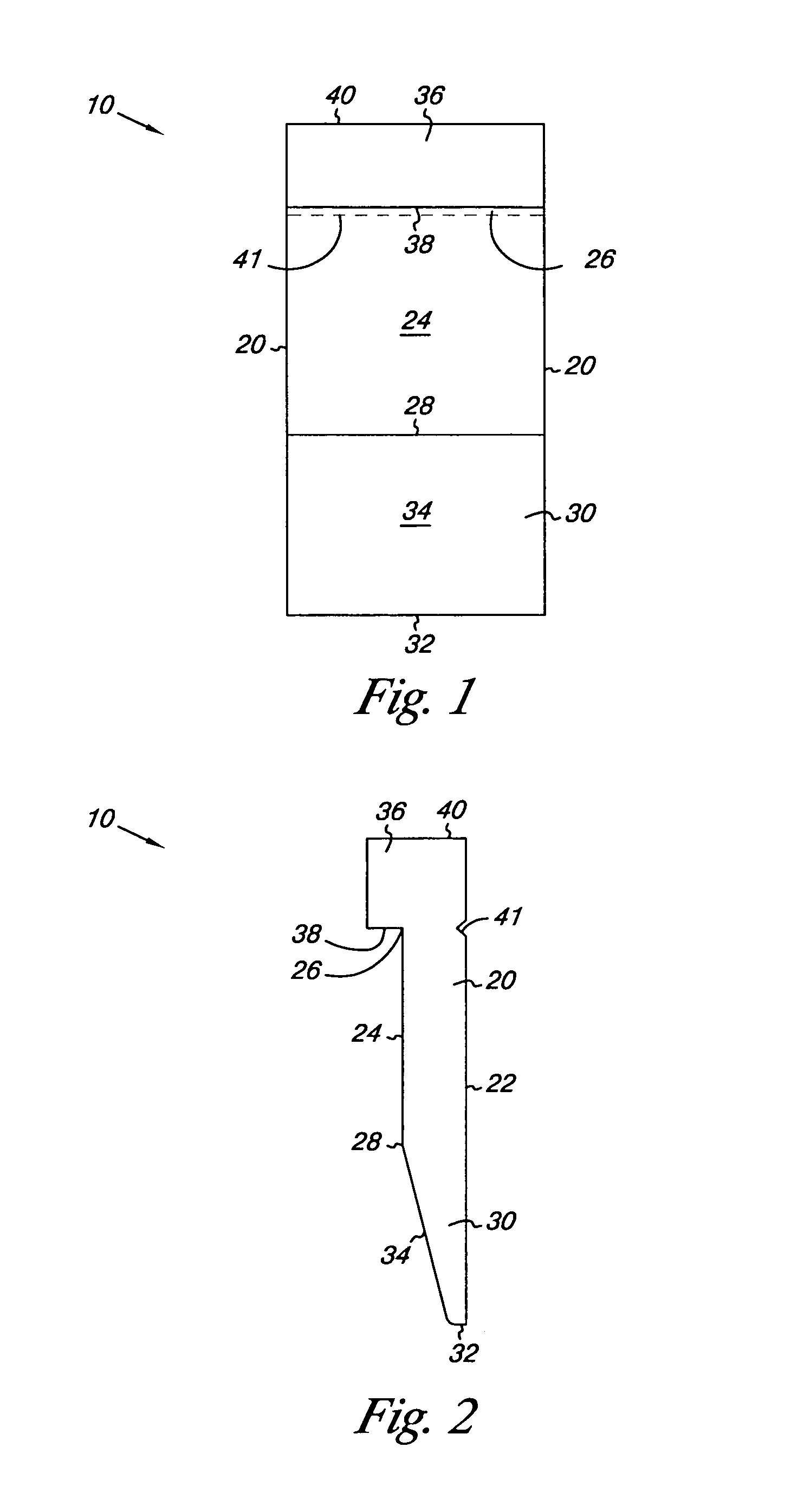
[0035]FIGS. 1 and 2 illustrate one of the spacers 10. FIGS. 3, 4, and 4a illustrate use of the spacers 10 to attach lengths of siding 16 (e.g., fiber cement lap siding such as “Hardiplank®” lap siding available from James Hardie Building Prod...


PUM


Abstract

Spacers and a spacing strip for use in an outer wall of a building between the outer vertical surface of its underlying structure and the inner surface of siding through which the siding is nailed to the underlying structure to provide a ventilation space between the rear surface of the siding and the outer surface of the underlying structure. Ventilation channels can be provided at both the lower and upper ends of the ventilation space to facilitate movement of air to the atmosphere from such a ventilation space.

Description

CROSS REFERENCE TO RELATED APPLICATION[0001]This application is a Continuation-in-Part of patent application Ser. No. 11 / 297,543 filed Dec. 8, 2005, the content of which application is hereby incorporated herein by reference.FIELD OF THE INVENTION[0002]The present invention relates to structures and methods adapted to provide ventilation between house siding and underlying house structure such as wind and water barrier covered sheathing attached to the outside of framing on the outside wall of the house.BACKGROUND[0003]It has been found that when certain types of house lap siding, particularly including fiber cement lap siding (e.g., “Hardiplank®” lap siding available from James Hardie Building Products, Mission Viejo, Calif.; or “WeatherBoard™” lap siding available from CertainTeed Corporation, Valley Forge, Pa.), is nailed directly to or over underlying structure such as polymeric house wrap (e.g., “Tyvec®” Home Wrap® available from DuPont) covered sheathing (e.g., sheets of press...

Claims


Application Information

Patent Timeline
Patent Type & Authority Patents(United States)
IPC IPC(8): E04F13/075E04B1/70
CPCE04F13/0864E04B1/70
Inventor JOHNSON, JAY A.CONROY, MICHAEL D.DANIELS, KURT D.
Owner FINN SYST
Why Eureka
Try Eureka