
Internal combustion engine system and misfire determining method for internal combustion engine

a technology of internal combustion engine and misfire determination, which is applied in the direction of electric control, instruments, propulsion by batteries/cells, etc., can solve the problems of difficult determination of misfire and misfire determination, and achieve the effect of more reliably and accurately determined

Active Publication Date: 2010-08-03
TOYOTA JIDOSHA KK
View PDF21 Cites 8 Cited by
  • Summary
  • Abstract
  • Description
  • Claims
  • Application Information

AI Technical Summary

Benefits of technology

The system enables more reliable and accurate misfire determination for multi-cylinder internal combustion engines outputting power via torsional elements, even during resonance conditions, by accounting for the influence components on rotation fluctuations.

Problems solved by technology

When the vibration control by the motor is conducted, determination of misfire becomes difficult with the conventional misfire determining method as in the above describe system, but the factor which makes determination of misfire difficult is not limited to such vibration control.
For example, when an engine is connected to a transmission or the like via a torsional element such as a damper which is used for the purpose of suppressing torque fluctuation of the engine, the entire transmission including the damper resonates depending on the operation point of the engine, and determination of misfire becomes difficult.

Method used


Image

  • Internal combustion engine system and misfire determining method for internal combustion engine
  • Internal combustion engine system and misfire determining method for internal combustion engine
  • Internal combustion engine system and misfire determining method for internal combustion engine

Examples


Embodiment Construction

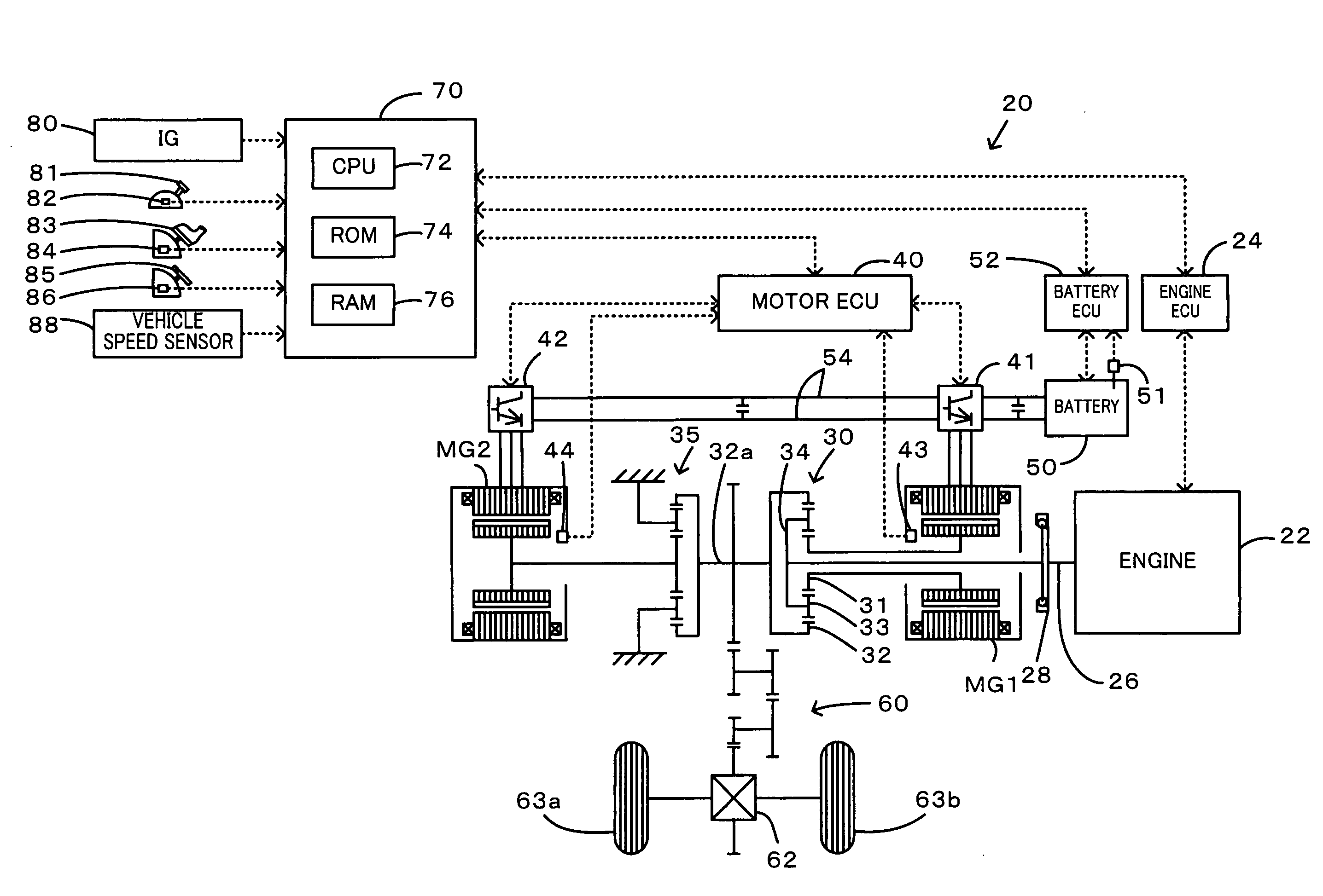
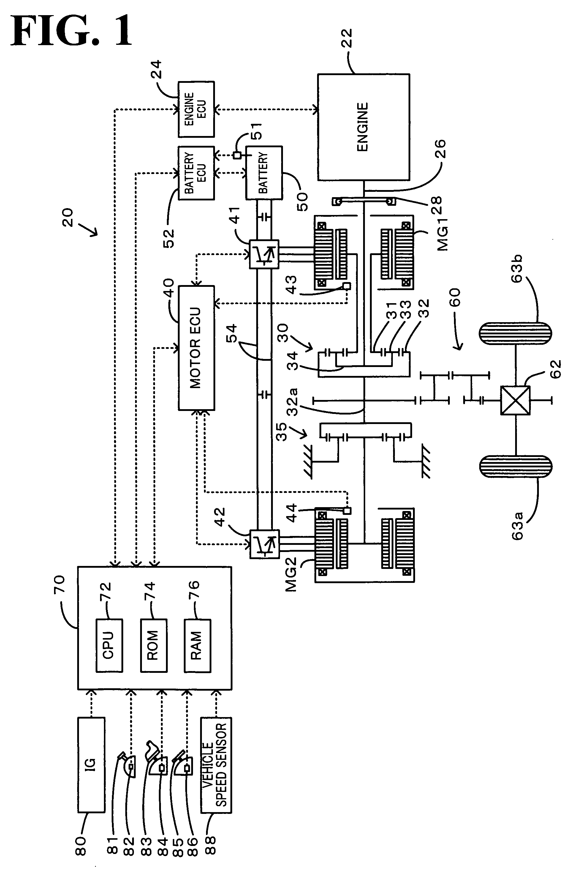
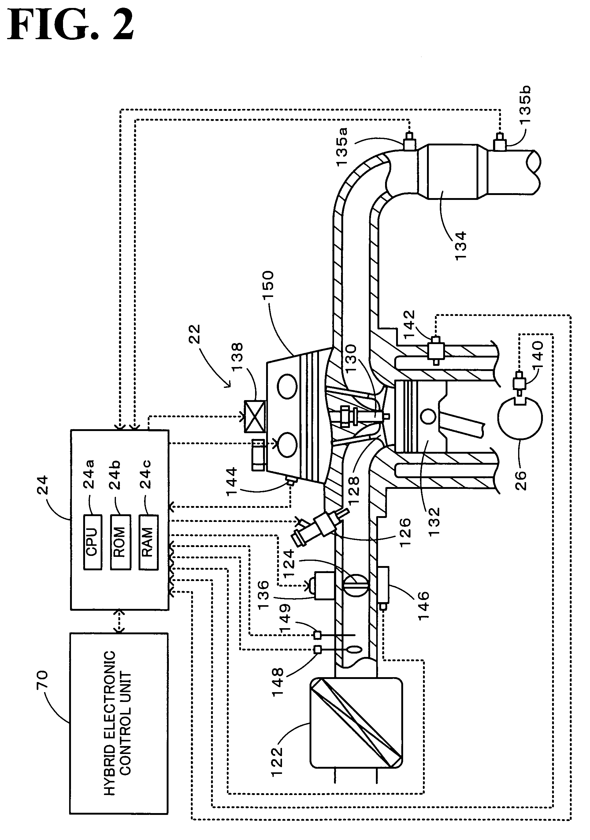
[0025]Next, the best mode for carrying out the present invention will be described by using an embodiment. FIG. 1 is a configuration diagram showing the outline of the configuration of a hybrid automobile 20 equipped with an internal combustion engine system which is one embodiment of the present invention. The hybrid automobile 20 of the embodiment includes an engine 22, a three-axis power distribution and integration mechanism 30 which is connected to a crankshaft 26 as an output shaft of the engine 22 via a damper 28 as a torsional element, a motor MG1 which is connected to the power distribution and integration mechanism 30 and capable of generating electric power, a reduction gear 35 mounted to a ring gear shaft 32a as a drive shaft connected to the power distribution and integration mechanism 30, a motor MG2 connected to the reduction gear 35, and a hybrid electronic control unit 70 which controls the entire vehicle. Here, the engine 22, the power distribution and integration ...


PUM


Abstract

An influence component N30m of every 30 degrees in a 30 degree rotation speed N30 base as time required for 30 degree rotation of a crankshaft is calculated by using a frequency characteristic of an influence given to a rotation fluctuation of a crankshaft by output torque output from a motor, which is calculated by using a mechanical model and an amplitude P and a phase q at a time of vibration control by the motor, a determination duration T30j is calculated by subtracting an influence component T30m as an inverse number of this from 30 degree duration T30, and misfire of an engine is determined by comparing the calculated determination duration T30j with a threshold value Tref. Thereby, misfire of the engine outputting power to a post-stage via a damper can be determined more reliably and accurately.

Description

TECHNICAL FIELD[0001]The present invention relates to an internal combustion engine system, a misfire determining method for an internal combustion engine, and a vehicle equipped with the internal combustion engine system, and more particularly relates to an internal combustion engine system having a multi-cylinder internal combustion engine capable of outputting power to a drive shaft via a torsional element, a misfire determining method for the multi-cylinder internal combustion engine capable of outputting power to the drive shaft via the torsional element, and a vehicle equipped with the internal combustion system.BACKGROUND ART[0002]Conventionally, as an internal combustion engine system of this kind, there is proposed the one that determines misfire of an engine based on a torque correction amount of a motor at the time of vibration control for canceling off a torque fluctuation of the engine by the motor in a vehicle mounted with the motor that is capable of generating electr...

Claims


Application Information

Patent Timeline
Patent Type & Authority Patents(United States)
IPC IPC(8): G01M15/11
CPCB60K6/24B60K6/445B60K6/448F02D29/02F02D29/06F02D41/1497G01M15/11F02D41/1498F02D2200/1015Y02T10/6243Y02T10/6295Y02T10/6239B60L2240/441B60L2270/145B60L50/16B60L50/61Y02T10/62Y02T10/70Y02T10/7072F02D45/00
Inventor SUZUKI
Owner TOYOTA JIDOSHA KK
Learn More