
Electrical component attachment structure for two-wheeled vehicle

a two-wheeled motor vehicle and electric component technology, applied in the direction of cycle equipment, transportation and packaging, cycle, etc., can solve the problems of limited degree of freedom in design regarding the arrangement thereof, affecting the appearance, and limiting the space near the engine, so as to achieve the effect of improving the layout design

Inactive Publication Date: 2010-08-03
HONDA MOTOR CO LTD
View PDF14 Cites 5 Cited by
  • Summary
  • Abstract
  • Description
  • Claims
  • Application Information

AI Technical Summary

Benefits of technology

[0006]The present invention has been made in view of the circumstance described above, and provides an electrical component attachment structure for a two-wheeled motor vehicle which allows the vicinity of an engine to be hardly affected by heat and leads to an improvement in the layout design near the engine.
[0008]With this configuration, even if an accessory having a large weight is arranged near the engine, the electrical component can be arranged in a position relatively close to the engine, and the effect of heat from the engine can be reduced compared to the related art. Further, the electrical component can be attached in a position which is hardly seen from the outside due to the center frame.
[0010]With this configuration, the influence of heat from the engine and the exhaust pipe can be reduced.
[0015]In the electrical component attachment structure for a two-wheeled motor vehicle according to the present invention, the electrical component is arranged behind the engine, on the vehicle inner side of the right and left center frames, and on the upper side of the drive chain. Thus, an accessory having a large weight can be arranged in the vicinity of the engine, and the center of gravity and balance of the vehicle body can be kept in a favorable state. Also, the electrical component can be arranged in a position relatively close to the engine while maintaining a good balance thereof, and arrangement with a main harness can be made easily. Further, since the electrical component can be hidden from the outside by the center frame, the electrical component is hardly seen from the exterior, thus improving the appearance.
[0016]Since the electrical component is attached to the center frame on the opposite side of the vehicle body as the exhaust pipe arranged on one side of the vehicle body, the effect of heat generated from the exhaust pipe can be reduced. Therefore, the reliability of the electrical component can be improved compared to the related art.
[0017]Further, since the interference prevention member which restricts the upward movement of the drive chain is provided between the drive chain and the electrical component, the drive chain first makes contact with the interference prevention member even if a trajectory of the drive chain comes close to the electrical component due to a swinging operation of the rear swing arm, a slack of the drive chain, or the like. Thus, the drive chain does not interfere with the electrical component. Accordingly, the reliability of the electrical component can be maintained in the same manner as in the related art.

Problems solved by technology

Thus, the degree of freedom in design regarding the arrangement thereof is limited.
However, the arranging of the electrical component above the transmission limits the space near the engine.
Further, since the vicinity of the engine is not covered by a side cover or the like, the electrical component can be seen from the outside of the vehicle, and the appearance may be spoiled.

Method used


Image

  • Electrical component attachment structure for two-wheeled vehicle
  • Electrical component attachment structure for two-wheeled vehicle
  • Electrical component attachment structure for two-wheeled vehicle

Examples


Embodiment Construction

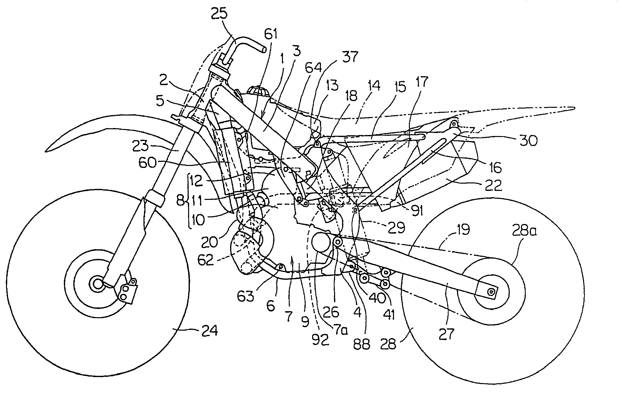
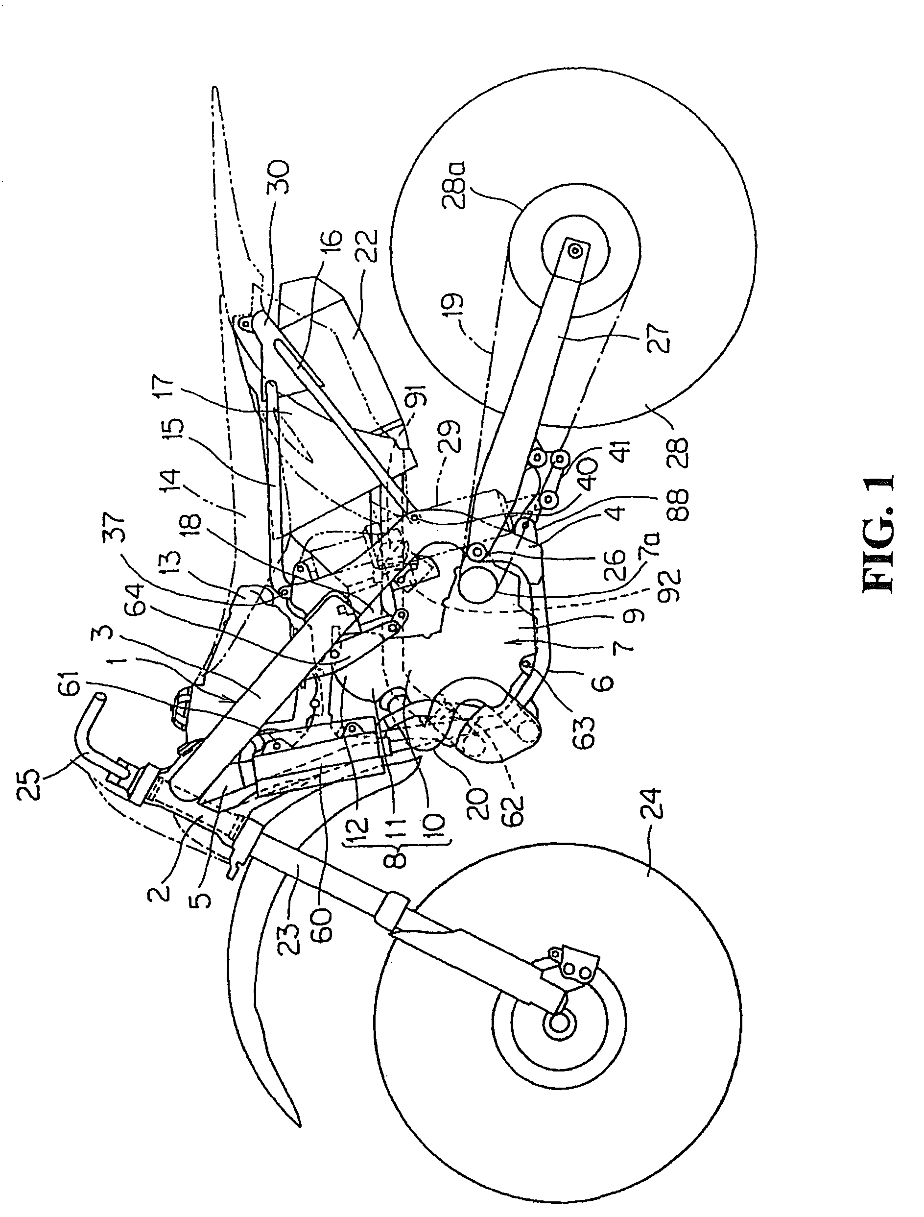
[0027]Hereinafter, one embodiment will be described based on the drawings. FIG. 1 is a side view of an off-road two-wheeled motor vehicle including an electrical component attachment structure for a two-wheeled motor vehicle according to the embodiment of the present invention.

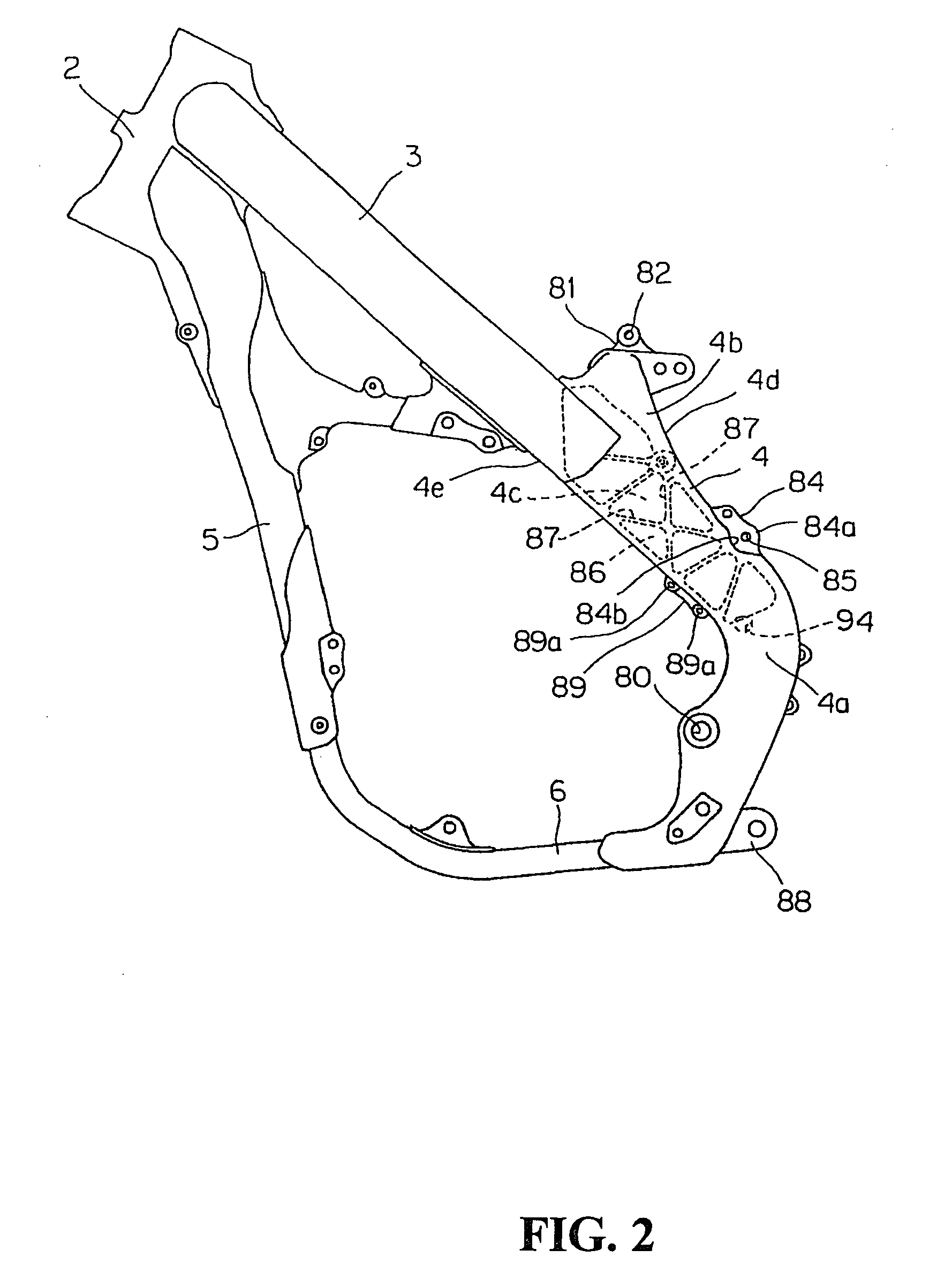
[0028]A vehicle body frame 1 of the two-wheeled motor vehicle includes a head pipe 2, a main frame 3, a center frame 4, a down frame 5, and a lower frame 6, which are connected in loop form to support an engine 7 in the inside thereof The engine 7 includes a cylinder 8 and a crank case 9. The main frame 3, the center frame 4, and the lower frame 6 are provided respectively in right and left as pairs, and the head pipe 2 and the down frame 5 are provided singularly along the center of the vehicle body.

[0029]The main frame 3 extends above the engine 7 obliquely downward and rearward in straight line, and is connected to an upper end section of the center frame 4 extending in the vertical direction behind the eng...


PUM


Abstract

A electrical component attachment structure for a two-wheeled motor vehicle includes a main frame supporting components of a vehicle body such as an engine, a pair of right and left center frames extending vertically behind the engine, and a rear swing arm swingably supported by a pivot shaft provided to the center frame. In this structure, a drive chain which transmits a driving force from the engine to a rear wheel is arranged along the rear swing arm. An electrical component is arranged on a vehicle inner side of the right and left center frames above the drive chain behind the engine.

Description

TECHNICAL FIELD[0001]The present invention relates to an electrical component attachment structure for a two-wheeled motor vehicle for attaching an electrical component in the inside of a vehicle body.BACKGROUND OF THE INVENTION[0002]As for conventional two-wheeled motor vehicles, there has been known a structure in which an electrical component such as a regulator is arranged above a transmission of an engine (for example, see Japanese Patent Application Publication No. 2005-219669). This regulator is connected to a modulator embedded in the transmission by wiring.[0003]However, when the electrical component is arranged near the engine, the electrical component needs to be laid out in a position where the effect of heat is small. Thus, the degree of freedom in design regarding the arrangement thereof is limited. It is also not preferable to provide a heat shield component as a measure against heat.[0004]When the balance of the vehicle body is taken into consideration, it is prefera...

Claims


Application Information

Patent Timeline
Patent Type & Authority Patents(United States)
IPC IPC(8): B62D61/02
CPCB62K11/04B62K19/30
Inventor KATO, YUICHINOGUCHI, YUJI
Owner HONDA MOTOR CO LTD
Learn More