
Bendable portion of an insertion tube of an endoscope and method of producing it

a technology of endoscopy and insertion tube, which is applied in the field of bendable portion, can solve problems such as extreme complexity

Inactive Publication Date: 2010-08-03
HENKE SASS WOLF
View PDF25 Cites 1299 Cited by
  • Summary
  • Abstract
  • Description
  • Claims
  • Application Information

AI Technical Summary

Benefits of technology

The present invention relates to a bendable portion for use in an endoscope or other medical instruments. The invention aims to simplify the production and mounting process of the bendable portion, to provide a smooth interior space for rinsing and suction operations, and to allow for the incorporation of lighting means and other necessary equipment without obstructing the interior space. The invention achieves these objectives by providing a bendable portion with a simplified interior space design that eliminates protruding wires and bolts, and by providing a method for producing the bendable portion that eliminates the need for additional connecting means. The invention also provides a design for the connecting means that allows for a smooth transition between the tube segments without the need for additional parts. Overall, the invention simplifies the production and mounting process of the bendable portion, improves its interior space, and allows for the incorporation of necessary equipment without obstructing the interior space.

Problems solved by technology

What all these known bendable portions have in common is that they consist of tube segments and of connecting parts, which are extremely complex with regard to their production, but especially also in respect of their mounting.

Method used


Image

  • Bendable portion of an insertion tube of an endoscope and method of producing it
  • Bendable portion of an insertion tube of an endoscope and method of producing it
  • Bendable portion of an insertion tube of an endoscope and method of producing it

Examples


Embodiment Construction

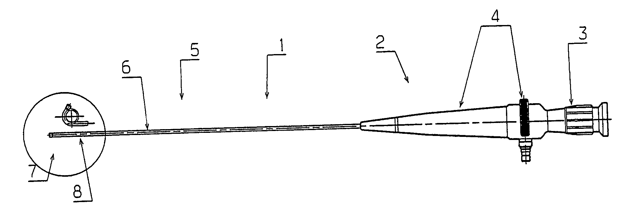
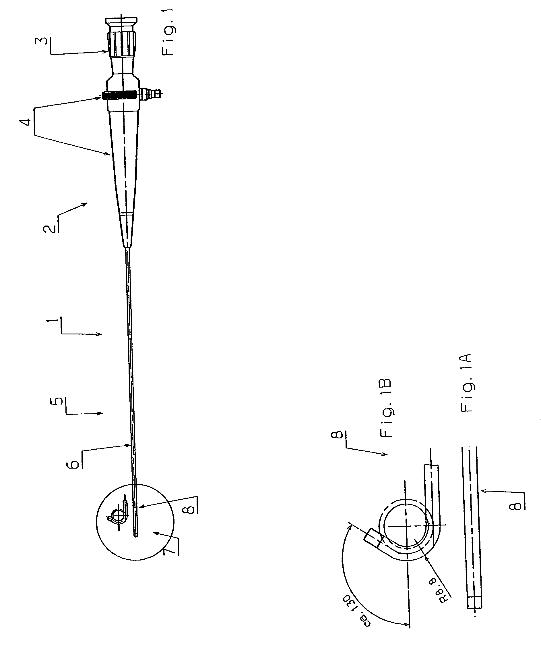
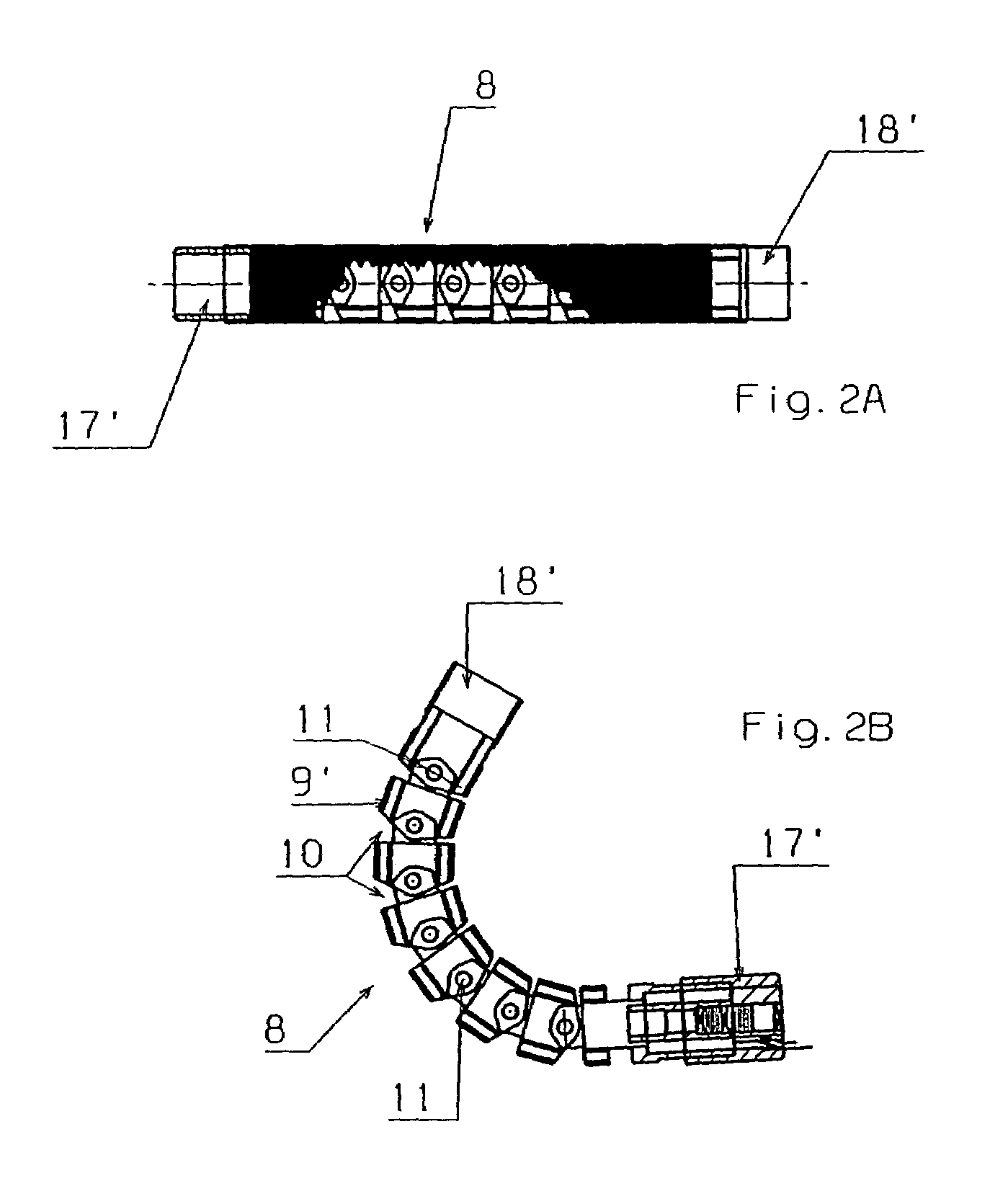
[0088]The endoscope 1 shown in FIG. 1 consists essentially of a proximal portion 2, which is intended for handling and operation and comprises an eye-piece 3 and a hand-operating element 4, and further of a distal portion 5, which is intended for insertion into a body cavity, is provided as an insertion tube 6, and comprises a bendable portion 8 at its distal end 7. This bendable portion 8 differs from e.g. a flexible insertion tube 6 in that said portion is bendable in a controlled manner, i.e. it can be bent in desired directions by the hand-operating element 4, as shown in FIGS. 1A and 1B. Whereas the insertion tube 6 may be simply provided as a flexible plastic tube, this is not possible for the controllable, bendable portion, which needs to be produced, as shown in FIGS. 2A and 2B, from individual tube segments 9, which are adjustable relative to each other and can be adjusted in the desired direction via control wires 10, said tube segments 9 being pivotably connected with eac...


PUM


Abstract

A bendable portion, which is arranged at the distal end of an insertion tube of an endoscope, comprises a plurality of tube segments, each of said tube segments having connecting means that cooperate with the connecting means of the adjacent tube segment, as well as control wires that can control the bending of the bendable portion. The respective connecting means of a tube segment are provided such that they axially protrude from the faces of the tube segment and are located within the mantle of the tube segment and such that they do not exceed the thickness of the mantle. The connecting means, which are provided on the respective faces of adjacent tube segments and which are located opposite each other, complement each other in the manner of a hinge-type connection.

Description

[0001]The current application claims the benefit of priority to German Patent Application No. DE 10 2004 027 850.4-55 filed on Jun. 8, 2004. Said application is incorporated by reference herein.FIELD OF THE INVENTION[0002]The invention relates to a bendable portion arranged at the distal end of an insertion tube of an endoscope, said bendable portion comprising a plurality of tube segments, each of which comprises a connecting portion that cooperates with the connecting portion of the adjacent tube segment, as well as control wires that control the bending of the bendable portion. The invention further relates to a method of producing such a bendable portion.BACKGROUND OF THE INVENTION[0003]Endoscopes comprising such bendable and controllable portions at the distal ends of their insertion tube are described in a great number of references, some of which shall be discussed in more detail below, such as DE 101 43 966 A1, DE 42 34 833 A1, EP 0 439 931 B1 and EP 1 090 581 B1.[0004]All o...

Claims


Application Information

Patent Timeline
Patent Type & Authority Patents(United States)
IPC IPC(8): A61B1/00A61B1/005
CPCA61B1/0011A61B1/0055A61B1/008
Inventor BRUNNEN, RAINER DIRKSIMON, THOMAS JURGEN
Owner HENKE SASS WOLF
Learn More