Image forming apparatus

a technology of image forming apparatus and forming device, which is applied in the direction of ohmic-resistance heating, instruments, and thermoplastic layer electrolysis processes, etc., can solve the problems of large quantity of energy required for heating and cooling steps, inability to properly separate recording material from the first fixing device, and inability to expect the release effect of wax components

Inactive Publication Date: 2010-08-03
CANON KK
View PDF6 Cites 1 Cited by
  • Summary
  • Abstract
  • Description
  • Claims
  • Application Information

AI Technical Summary

Problems solved by technology

However, the configurations disclosed in Japanese Patent Laid-Open Nos. 2004-205563 and 2006-250979 may cause the problem described below.
Specifically, in spite of heating and pressing treatment in a degree which allows the toner to be temporarily fixed to the transparent resin layer, there may be caused the phenomenon that the recording material cannot be properly separated from the first fixing device due to the transparent resin layer on the surface of the recording material.
In particular, the problem is significant when a resin not containing a wax component is used in the transparent resin layer of the recording material in view of compatibility with the toner.
This is because the releasing effect of the wax component cannot be expected.
When the thickness of the recording material is increased for preventing defective separation, a large quantity of energy is required for the heating and cooling steps.
Therefore, this method is not a measure for resolving the problem.

Method used


Image

  • Image forming apparatus
  • Image forming apparatus
  • Image forming apparatus

Examples


first embodiment

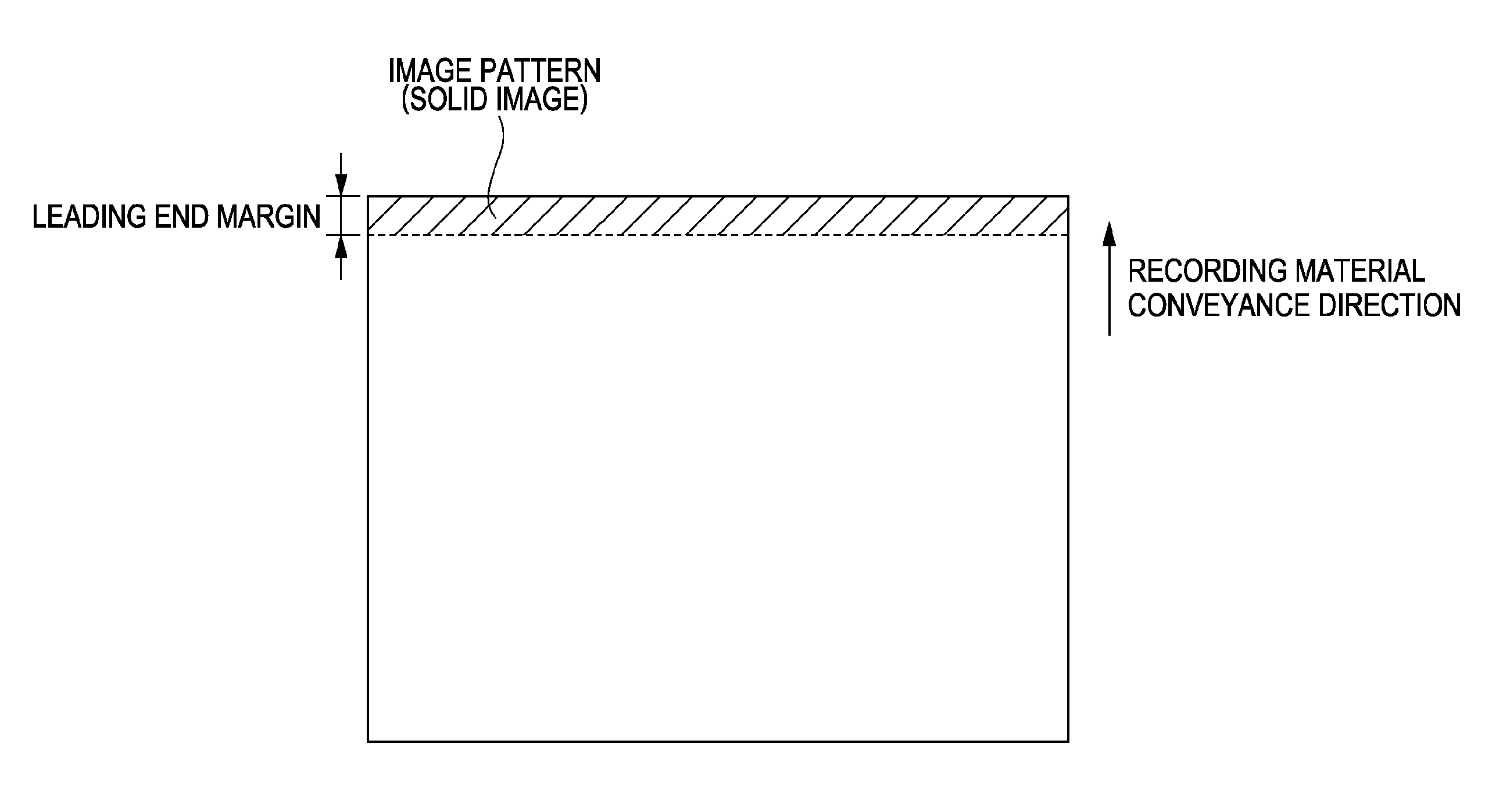
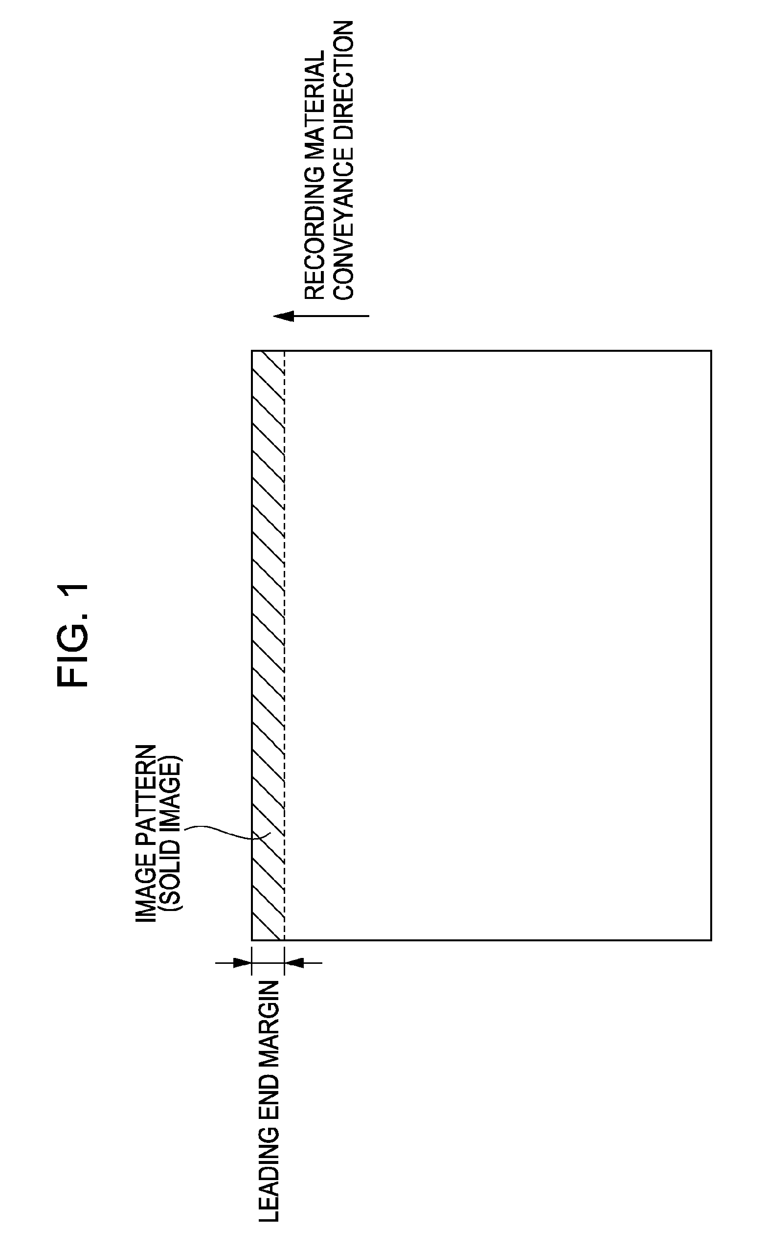
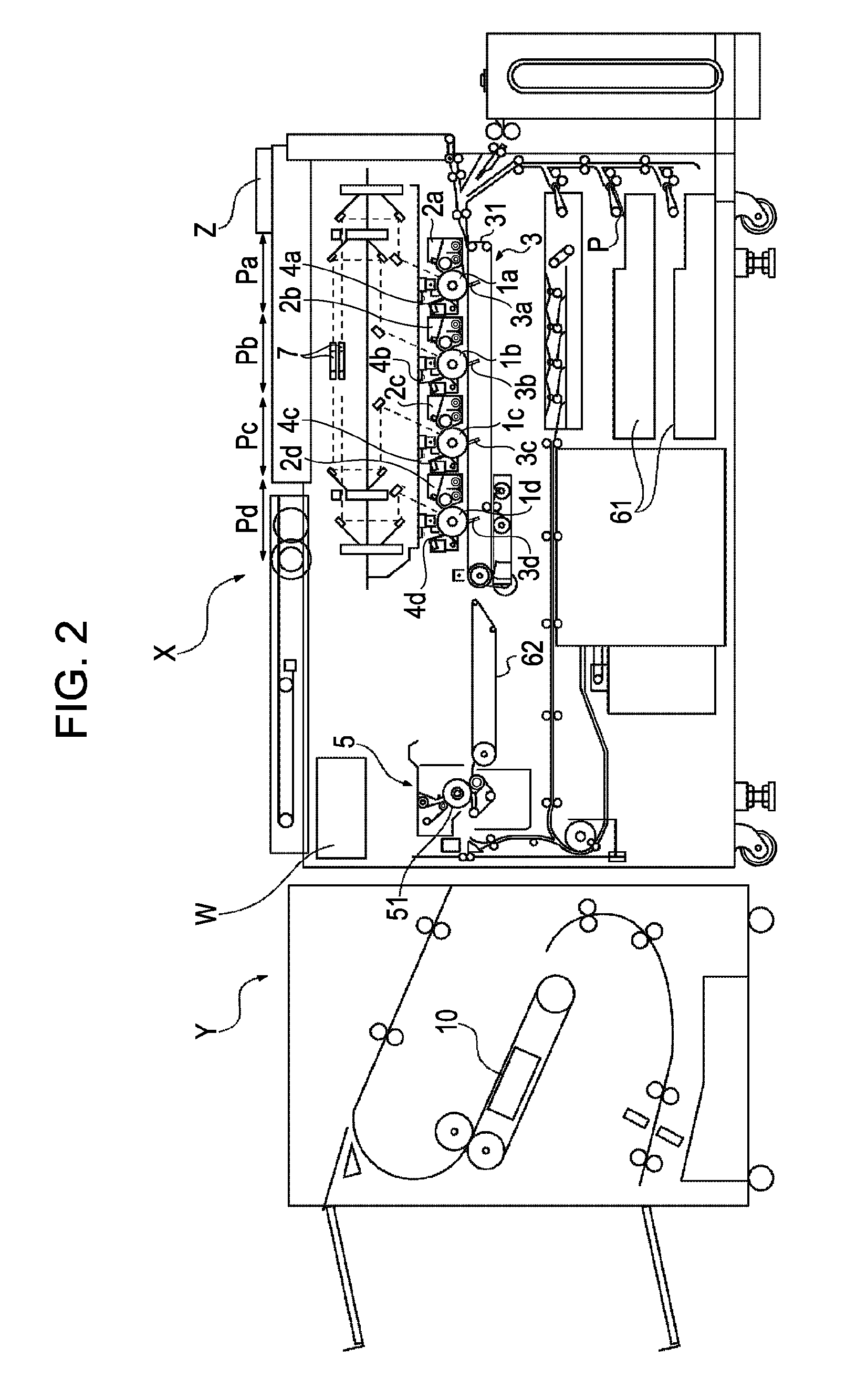
[0031]An example of an image forming system provided with a full-color copying machine is described with reference to the drawings. In this example, as shown in FIG. 2, an image forming system includes an image forming apparatus X and a glossing unit Y. The image forming apparatus X is configured to function independently as a copying machine as shown in FIG. 6. The glossing unit Y is an optional apparatus which can be attached and / or detached according to user's demand. In other words, the glossing unit Y is detachable from the image forming apparatus X. As another example of an image forming system, another image forming apparatus may be used, in which the image forming apparatus X and the glossing unit Y cannot be separated from each other, and the two functions of the image forming apparatus X and the glossing unit Y are integrated.

(Image Forming Portion)

[0032]First, an image forming portion is described with reference to FIGS. 2 and 3. The configuration shown in FIG. 6 is subst...

example 2

[0118]Next, Example 2 is described. In Example 1, a predetermined image pattern is formed in the margin at the leading end of the photo-medium using color toners of yellow, magenta, cyan, and black. However, in this example, a transparent toner is used. Since the other configuration is the same as in Example 1, a description thereof is omitted.

[0119]The transparent toner does not contain a colorant, and a resin material which constitutes the toner is the same as in the color toners. Namely, the transparent toner contains a polyester resin containing 5 parts by weight of a wax component dispersed therein. The glass transition temperature of the transparent toner is also 55° C. The transparent toner used in this example is white in an unfixed state, but toner particle lumps are integrated by melting and become colorless and transparent after fixing.

[0120]In this example, the separability of the photo-medium and fixability in the fixing device were evaluated to obtain the same results ...

example 3

[0127]Next, Example 3 is described. In this example, as in Example 2, a predetermined image pattern is formed using a transparent toner in a margin at the leading end of a photo-medium, but the composition of the transparent toner is different in Example 2. The other configuration is the same as in Examples 1 and 2, and thus a description thereof is omitted.

[0128]Specifically, the resin component of the transparent toner used in this example has a wax component content different from that of the other color toners. Namely, the wax component content in the transparent toner is higher than that of the other color toners.

[0129]This is because although the conditions of the materials used for the color toners are limited in view of reproducibility and glossiness when a full-color image is formed, the transparent toner does not have such a limitation. In other words, the separability of the photo-medium in the fixing device is further improved by changing the material composition of the ...


PUM


Abstract

A fixing step before smoothing by a smoothing device causes the phenomenon that a photo-medium is not properly separated from a fixing device due to a toner receiving layer of the photo-medium. Therefore, in order to prevent the occurrence of defective separation in the fixing device, a predetermined image pattern is formed using a toner containing a wax component in a margin, i.e., a non-image forming region, at the leading end of the photo-medium.

Description

BACKGROUND OF THE INVENTION[0001]1. Field of the Invention[0002]The present invention relates to an image forming system for forming an image on a recording material. Specifically, the present invention relates to an image forming system for obtaining an output with a smooth surface using a recording material having a surface provided with a toner receiving layer composed of a thermoplastic resin.[0003]The image forming system can be used for, for example, a copying machine, a printer, and FAX, which form images by an electrophotographic system, and a compound machine having the functions of these apparatuses.[0004]2. Description of the Related Art[0005]Many image forming apparatuses for forming full-color images have been commercialized and requirements for image quality have been increasingly advanced with use in various fields.[0006]In particular, in order to improve the quality of full-color images, it is required to improve image glossiness. One of factors which determine the g...

Claims


Application Information

Patent Timeline
Patent Type & Authority Patents(United States)
IPC IPC(8): G03G15/20G03G15/16H05B11/00
CPCG03G15/6585G03G2215/00805
Inventor ISHIZUKA, JIRO
Owner CANON KK
Why Eureka
Try Eureka