
System and method to improve WLAN handover behavior at entry/exit points

a handover behavior and system technology, applied in the field of wireless communication, can solve the problems of consuming a significant amount of battery power, affecting the handover behavior of wan systems, so as to improve the handover behavior of wan devices, prevent unnecessary loads on wan systems, and save costs

Inactive Publication Date: 2010-08-03
GOOGLE TECH HLDG LLC
View PDF30 Cites 6 Cited by
  • Summary
  • Abstract
  • Description
  • Claims
  • Application Information

AI Technical Summary

Benefits of technology

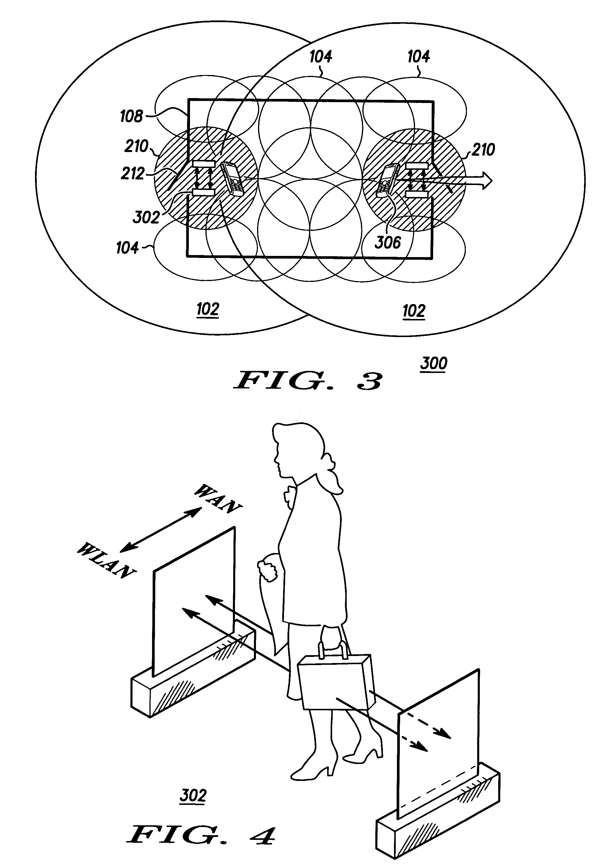
[0010]Briefly, in accordance with preferred embodiments of the present invention, disclosed are a system, method, mobile subscriber device, and computer readable medium for improving WLAN handover behavior at entry / exit points. In accordance with a preferred embodiment of the present invention, a system, computer readable medium, mobile subscriber device and method detect two consecutive signals from at least one egress portal, determine that the wireless device is moving from the coverage area of a first communications system to the coverage area of a second communications system according to the order of signals received from the egress portal, initiate a registration sequence with the second wireless communication system in response to determining that the wireless device is moving from the coverage area of the first communications system to the coverage area of the second communications system, and conduct present and subsequent calls via the second wireless communication system.
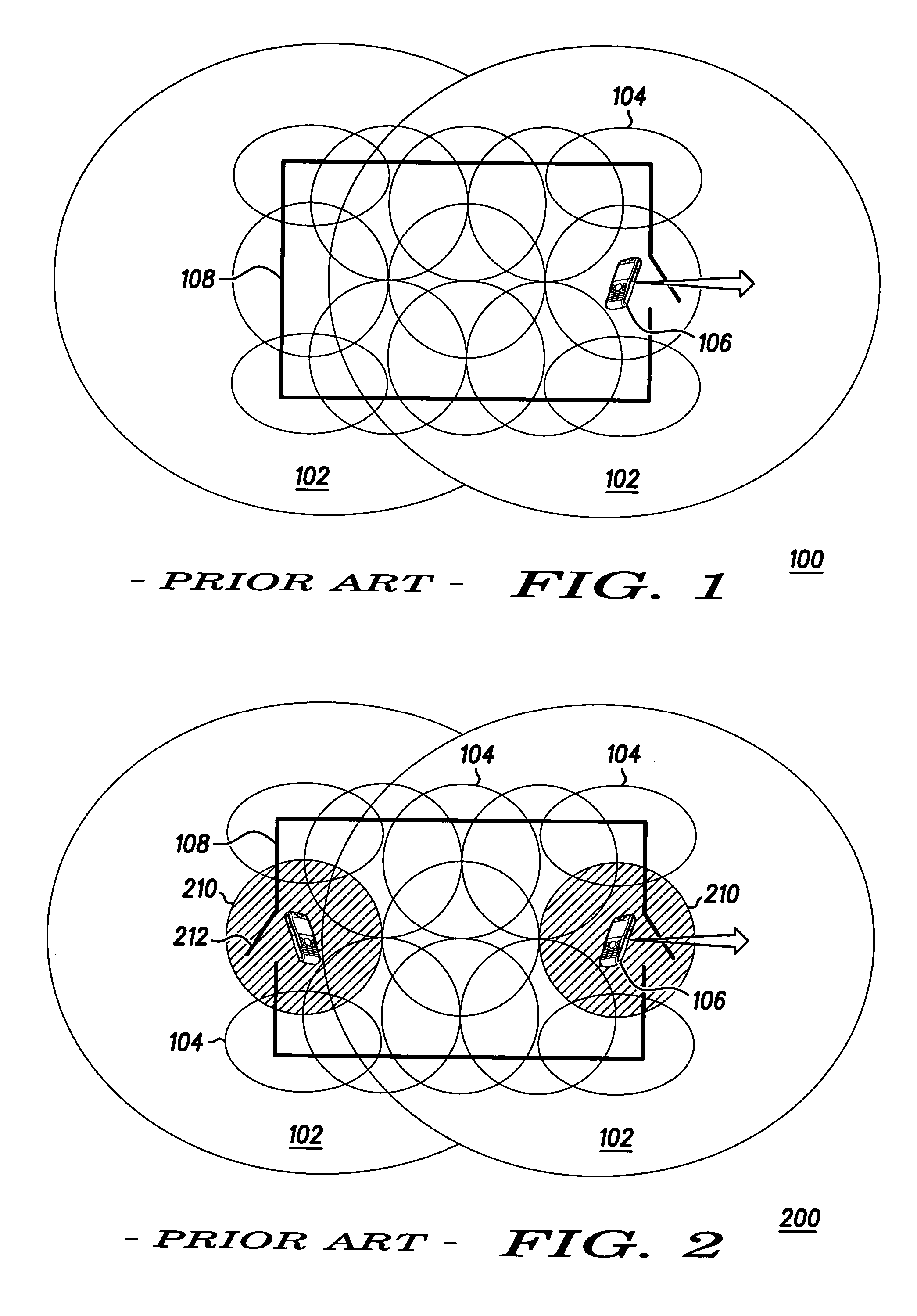
[0017]The preferred embodiments of the present invention are advantageous because they allow the wireless device to make a more intelligent decision as to whether or not to perform checks for an alternative system, whether or not to initiate a registration, and whether or not to handover a call to another network based on the actual movement of the wireless device. This prevents unnecessary loads on a WAN system, thereby saving cost, and increases the battery life of the wireless device. The benefits are especially noticed by users who spend prolonged periods of time in border cell areas, typically causing the wireless devices to run both a WLAN stack and a cellular (WAN) stack simultaneously.

Problems solved by technology

Battery life may be degraded on one system in comparison to another as the hardware required to operate in that particular mode may consume more energy than in another mode.
Also, cost may be significantly different from one system to another and the subscriber may pay a premium to be able to use a particular network.
These multi-mode devices, which are capable of operating on WLAN and WAN systems, can consume a significant amount of battery power looking for service on the WAN while camped on the WLAN.
Some of this is purely wasted energy when WLAN coverage is good, and given that WLAN is the preferred connection, WAN background scans are unnecessary.
However, in the event that the device knows nothing about the WAN service, it must go on the assumption that it could take minutes to find an acceptable service and therefore, should begin searching immediately.
Even if a service is found, that operator may not support the desired feature set for an application of interest requiring the device to move on and continue looking, or settle for what can be provided.
This not only wastes time, but also uses extra battery life.
In most instances, the burden to decide when to hand over to the other system is placed upon the actual subscriber device.
However, due to the non-uniform nature of coverage caused by building structure, obstructions etc., making an accurate reliable decision to initiate the handover of the call from one system to another is difficult and error-prone.
Scanning both systems costs battery life on the Mobile Device.
Furthermore, the presence of any WLAN coverage holes inside the building complicates this decision making process and may result in short WAN calls when the user walks through a WLAN coverage hole, say in a stairwell for example.
The problem with this method is that there is significant detrimental effect on battery life because the device must operate both sets of hardware simultaneously.
Moreover, there is actually an inherent degradation in battery life of these devices in comparison to single-mode devices due to the additional power required by the WLAN chipsets.

Method used


Image

  • System and method to improve WLAN handover behavior at entry/exit points
  • System and method to improve WLAN handover behavior at entry/exit points
  • System and method to improve WLAN handover behavior at entry/exit points

Examples


Embodiment Construction

[0030]As required, detailed embodiments of the present invention are disclosed herein; however, it is to be understood that the disclosed embodiments are merely exemplary of the invention, which can be embodied in various forms. Therefore, specific structural and functional details disclosed herein are not to be interpreted as limiting, but merely as a basis for the claims and as a representative basis for teaching one skilled in the art to variously employ the present invention in virtually any appropriately detailed structure. Further, the terms and phrases used herein are not intended to be limiting; but rather, to provide an understandable description of the invention.

[0031]The terms “a” or “an”, as used herein, are defined as one or more than one. The term plurality, as used herein, is defined as two or more than two. The term another, as used herein, is defined as at least a second or more. The terms including and / or having, as used herein, are defined as comprising (i.e., ope...


PUM


Abstract

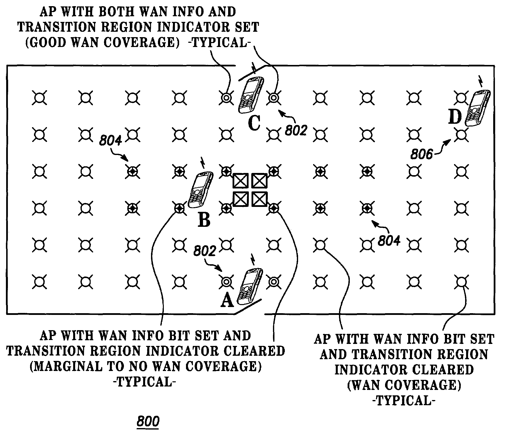
A system, wireless device (306) and method determine that a wireless device (306) is detecting a triggering event. The triggering event includes detecting a WLAN border cell (210), detecting a first signal from an egress portal (302), or detecting a degradation in signal quality. The wireless device (306) then detects at least one signal from an egress portal (302), determines that the wireless device (306) is moving from the coverage area of a first communications system to the coverage area of a second communications system according to the order of signals received from the egress portal (302), initiates a registration sequence with the second wireless communication system in response to determining that the wireless device (306) is moving from the coverage area of the first communications system to the coverage area of the second communications system, and conducts present and subsequent calls via the second wireless communication system.

Description

CROSS-REFERENCE TO RELATED APPLICATION[0001]The present patent application is related to co-pending and commonly owned U.S. patent application Ser. No. 10 / 649,999, entitled “SYSTEM AND METHOD TO IMPROVE WLAN HANDOVER BEHAVIOR AND PHONE BATTERY LIFE WHEN STATIONARY IN BORDER CELLS”, filed on even date with the present patent application, the entire teachings of which being hereby incorporated by reference.FIELD OF THE INVENTION[0002]The present invention generally relates to the field of wireless communications, and more particularly relates to a system and method to improve handover behavior between WLANs and WANs at exit points.BACKGROUND OF THE INVENTION[0003]Many cellular communication systems consist of a combination of different types of systems and protocols. Likewise, many of the devices used on these networks, such as cellular telephones and handheld personal data assistants, are designed to be multi-mode devices, i.e. will operate on multiple networks. Ideally, there should...

Claims


Application Information

Patent Timeline
Patent Type & Authority Patents(United States)
IPC IPC(8): H04W4/00H04W36/00H04L12/28H04W36/14
CPCH04W36/32H04W24/00H04W36/14H04W60/00H04W84/12
Inventor DORENBOSCH, JHEROEN P.GIPSON, JACK ANTHONYHUFFERD, III, LOWELL C.HIRSBRUNNER, ALEX P.BELKIN, ANATOLY S.ALEN, ANAND BERNARDSTORM, BRIAN D.
Owner GOOGLE TECH HLDG LLC
Learn More