
Valve with freeze-proof heated valve seat

a valve seat and valve seat technology, applied in water supply installation, electrochemical generators, light and heating equipment, etc., can solve problems such as shutting down of fuel cell systems and interference with system proper operation, and achieve the effect of avoiding overheating of valves and facilitating operation and assembly of valves

Active Publication Date: 2010-08-10
PARKER INTANGIBLES LLC
View PDF13 Cites 7 Cited by
  • Summary
  • Abstract
  • Description
  • Claims
  • Application Information

AI Technical Summary

Benefits of technology

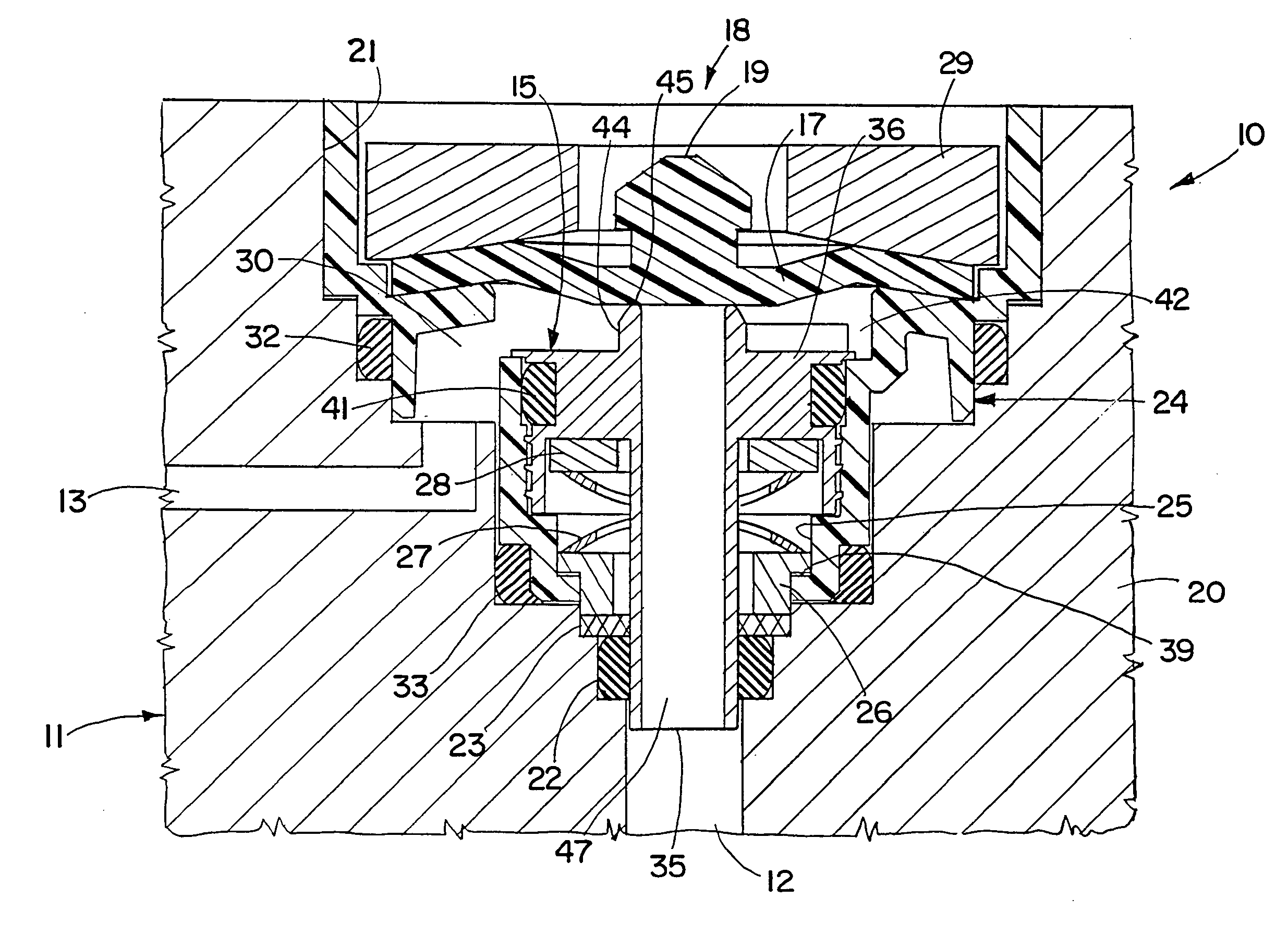
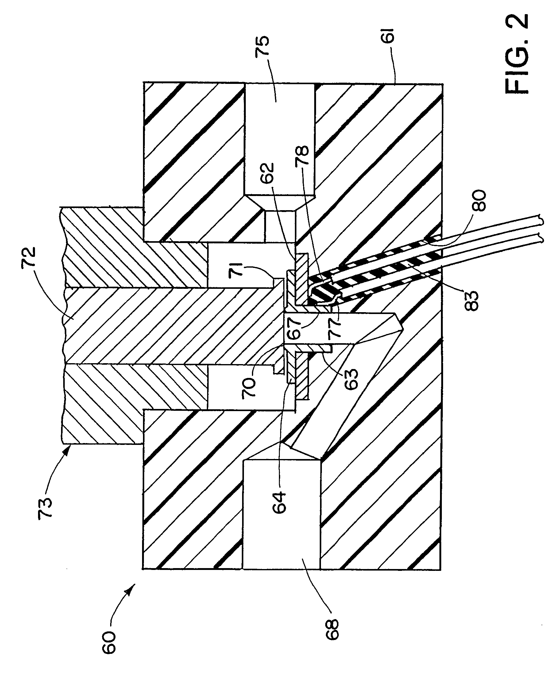
[0005]The present invention provides several inventive features operative separately or in combination to provide a freeze-proof valve, specifically a freeze-proof drain and / or vent valve having particular application in fuel cell systems. These features include the utilization of a positive temperature coefficient (PTC) heating element for heating the valve in an energy efficient manner that also avoids overheating of the valve, the integration of a heater into a valve in a manner where a valve seat is used as an electrical conductor to facilitate operation and assembly of the valve, the use of a heater internal to the valve for direct heating of the valve seat, and a unique valve construction that provides for self-draining to avoid accumulation of water or other liquid in the valve that might negatively impact performance of the valve.

Problems solved by technology

A problem arises when the fuel cell system shuts down under ambient freezing conditions.
Water frozen on the valve seat may cause the valve not to open and / or close properly, and thereby interfere with proper operation of the system.
This was considered undesirable because of the requirement for additional heating means to thaw ice in the drain valve and the substantial amount of thawing time and thawing power needed.

Method used


Image

  • Valve with freeze-proof heated valve seat
  • Valve with freeze-proof heated valve seat
  • Valve with freeze-proof heated valve seat

Examples


Embodiment Construction

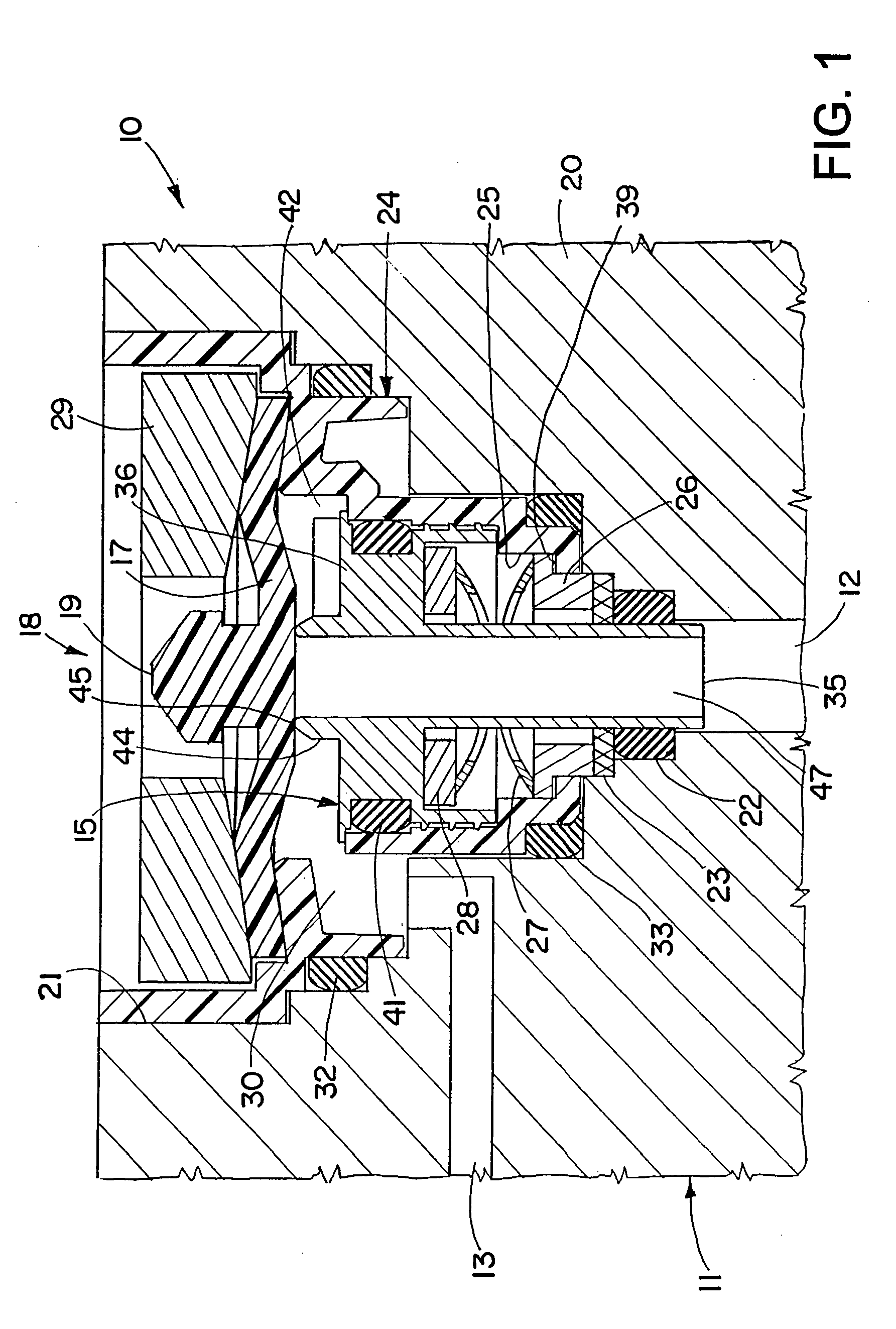
[0027]Referring now in detail to the drawings and initially to FIG. 1, an exemplary valve according to the invention is designated generally by reference numeral 10. The valve 10 generally comprises a valve body 11 having a fluid inlet 12 and a fluid outlet 13. As will be appreciated by those skilled in the art, the valve may be used in systems where flow is from the fluid outlet to the fluid inlet, although for most freeze-proof applications flow will be from the fluid inlet to the fluid outlet.

[0028]A valve seat 15, which may also be referred to as a valve orifice, is located in the valve body 11 between the fluid inlet and the fluid outlet, and a valve member 17 is movable towards and away from the valve seat 15 for controlling the flow of fluid from the fluid inlet to the fluid outlet. The valve member 17 may be actuated by any suitable means such as by a solenoid, fluid pressure, etc., depending on the particular application. In most fuel cell applications, the valve member wil...


PUM


Abstract

A valve comprises a valve body having a fluid inlet and fluid outlet, a valve seat located in the valve body between the fluid inlet and a fluid outlet, a valve member movable towards and away from the valve seat for controlling the flow of fluid from the fluid inlet to the fluid outlet, and a PTC heater in thermal contact with the valve seat for heating the valve seat. The heater is integrated in the valve in a manner where the valve seat is used as an electrical conductor to facilitate operation and assembly of the valve, and a unique valve construction is provided for enabling self-draining to avoid accumulation of water or other liquid in the valve that might negatively impact performance of the valve.

Description

RELATED APPLICATION DATA[0001]This application claims the benefit of U.S. Provisional Application No. 60 / 807,224 filed Jul. 13, 2006, which is hereby incorporated herein by reference in its entirety.FIELD OF THE INVENTION[0002]The herein described invention relates generally to freeze-proof valves and more particularly to valves with freeze-proof valve seats used in fuel cell systems.BACKGROUND OF THE INVENTION[0003]Fuel cell systems heretofore have used drain valves for controlling the draining of water to a drain. A problem arises when the fuel cell system shuts down under ambient freezing conditions. Water frozen on the valve seat may cause the valve not to open and / or close properly, and thereby interfere with proper operation of the system.[0004]According to U.S. Published Patent Application No. 2007 / 0141419, heating wires heretofore have been wound around the drain valves thereby to heat the valve prior to re-start of the fuel cell system. This was considered undesirable becau...

Claims


Application Information

Patent Timeline
Patent Type & Authority Patents(United States)
IPC IPC(8): F16K49/00F24J3/00
CPCF16K49/002H01M8/04156H01M8/04253Y02E60/50Y10T137/0318Y10T137/6606
Inventor KNIGHT, STEVEN R.NEAL, TIMOTHY P.
Owner PARKER INTANGIBLES LLC
Learn More