Sill flashing and associated method

a technology of sliding and associated methods, which is applied in the field of sliding flashing, can solve the problems of window sill damage, window water entering the sill, and the material of the barrier material not normally providing a waterproof barrier on the inner surface of the rough opening, and achieves the effect of facilitating the installation of the barrier material

Active Publication Date: 2010-08-17
ALLEN L ROSS
View PDF50 Cites 34 Cited by
  • Summary
  • Abstract
  • Description
  • Claims
  • Application Information

AI Technical Summary

Benefits of technology

[0010]According to one embodiment of the present invention, there is provided a sill flashing for use in the installation of a portal, such as a window, in an opening of a wall. The flashing defines channels for directing water out of the wall, thereby restricting the passage of water into the wall around the portal. As discussed below, the flashing can include one or more integral housing that can be used to overlap an adjacent part of the flashing to prevent leakage at an interface of adjacent parts of the flashing. The flashing can facilitate the installation thereof, e.g., so that the conventional methods for cutting the inner surface of the wall without damaging the flashing, so that the flashing can be installed in a variety of weather condition without tape or adhesives, and / or so that shims can easily be used in connection with the flashing installation.
[0014]The rear dam can be configured to define a top edge that is substantially coplanar with the upper end of the support portions so that the support portions and the rear dam are configured to cooperatively provide support for a portal disposed in the opening. In some cases, the sill portion defines a dam height of at least ⅜ inch when the lower ends of the support portions are disposed horizontally on the sill of the opening, the dam height being measured in a vertical direction from a top of the rear dam to an intersection of the base portions and the front face plate. The rear dam can define an offset portion proximate the jamb portion that is offset in a direction toward the front face plate, and / or the rear dam can define a reinforcement member proximate the jamb portion, e.g., to prevent cutting or other damage to the rear dam during drywall installation.
[0016]According to one embodiment, the sill portion also defines a longitudinal shelf that extends from the rear dam in a direction opposite the front face plate. As described below, the shelf can increase the usefulness of the flashing, e.g., by allowing a flashing with a particular configuration to be used in different installations with windows or other portals of various dimensions. The shelf can define a gap proximate each housing.

Problems solved by technology

The barrier material forms a moisture barrier extending over the outer surface, but, due to the cuts, the barrier material does not normally provide a waterproof barrier on the inner surfaces of the rough opening.
However, in some cases, the window can leak water to the sill.
Thus, the water can flow into the wall, i.e., between the inner and outer surfaces of the wall, causing damage to the wall.
While such back dams generally decrease the likelihood of water passing under the sill and into the building, the back dam can increase the complexity of the installation of the window.
Further, since the flashing is disposed in the opening and nailed in place before the window is positioned, shims cannot be inserted below the flashing without removing the window and flashing or deforming the flashing.
In some cases, the window must be removed in order to place the shims on the flashing, or the installer may simply omit the shims, such that the window may not be properly horizontally positioned.
This relative difference in size between the window and the opening provides space for the insertion of shims around the window and typically results in a small space or gap around the window.
Unfortunately, when the router is moved against a flashing, the router may cut through the flashing.
As the router contacts the back dam of the flashing, the back dam can be cut or otherwise damaged, thereby potentially reducing the effectiveness of the back dam for preventing water intrusion.
Further, a conventional back dam extends upward beyond the bottom of the window and is disposed against the inside surface of the window, such that the height of a conventional back dam is restricted by the configuration of the window.
For example, the back dam typically cannot have a height that is greater than the height of the bottom frame or sill of the window, as a higher back dam would extend upward beyond the bottom frame resulting in an aesthetically undesirable appearance.
Thus, if a planar member, such as an interior wood frame or a sheet of drywall, is disposed against the inside surface of the window, the additional thickness of the back dam at the bottom of the window results in a gap between the planar member and the window frame at the sides and top of the window.
Such a gap reduces the aesthetic appearance of the window installation and / or complicates the installation by requiring additional steps for eliminating or covering the gap.

Method used


Image

  • Sill flashing and associated method
  • Sill flashing and associated method
  • Sill flashing and associated method

Examples


Embodiment Construction

[0041]The present invention now will be described more fully hereinafter with reference to the accompanying drawings, in which preferred embodiments of the invention are shown. This invention may, however, be embodied in many different forms and should not be construed as limited to the embodiments set forth herein; rather, these embodiments are provided so that this disclosure will be thorough and complete, and will fully convey the scope of the invention to those skilled in the art. Like numbers refer to like elements throughout.

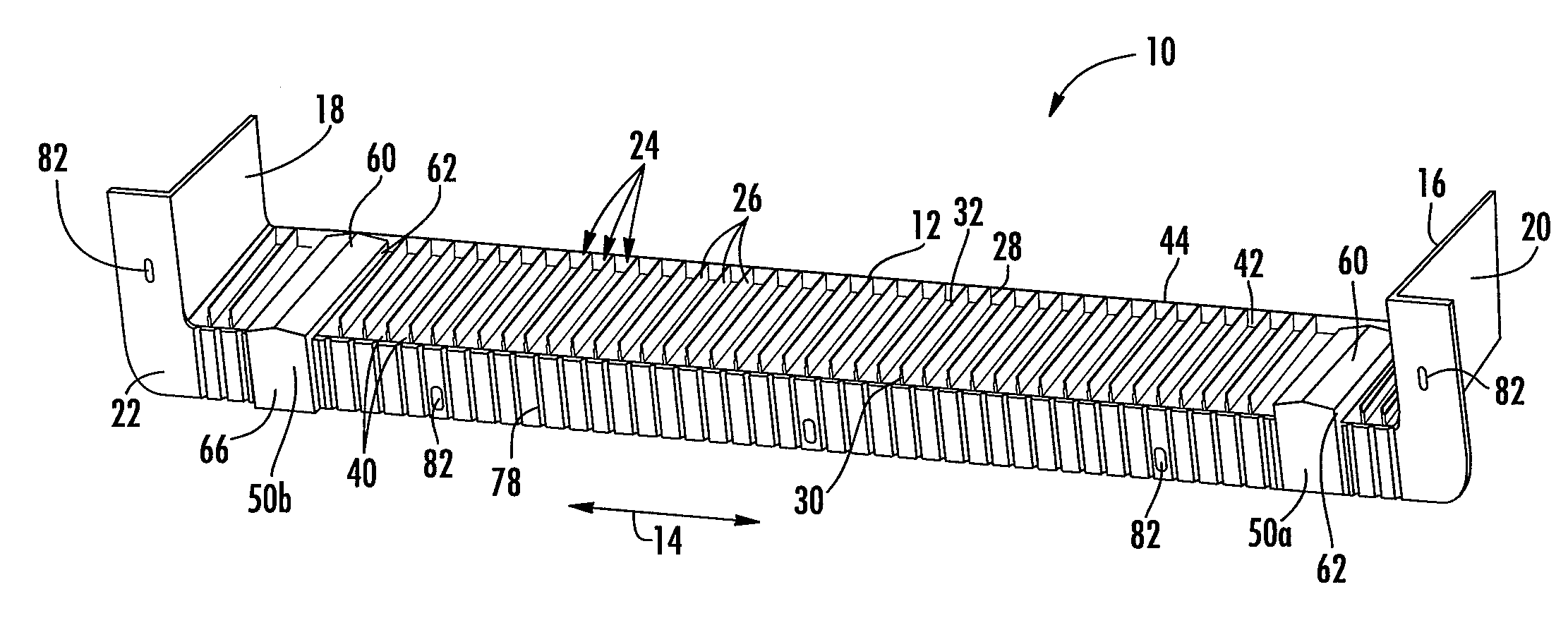
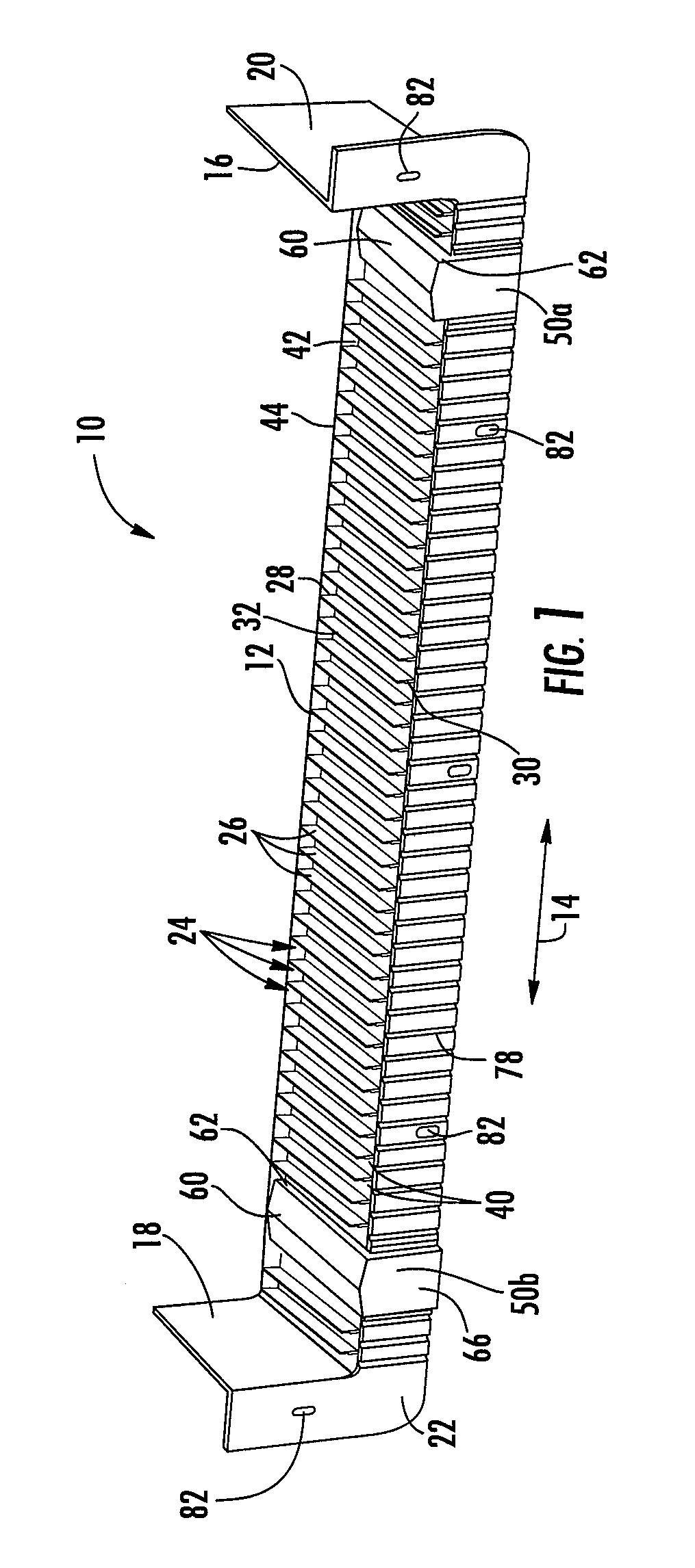
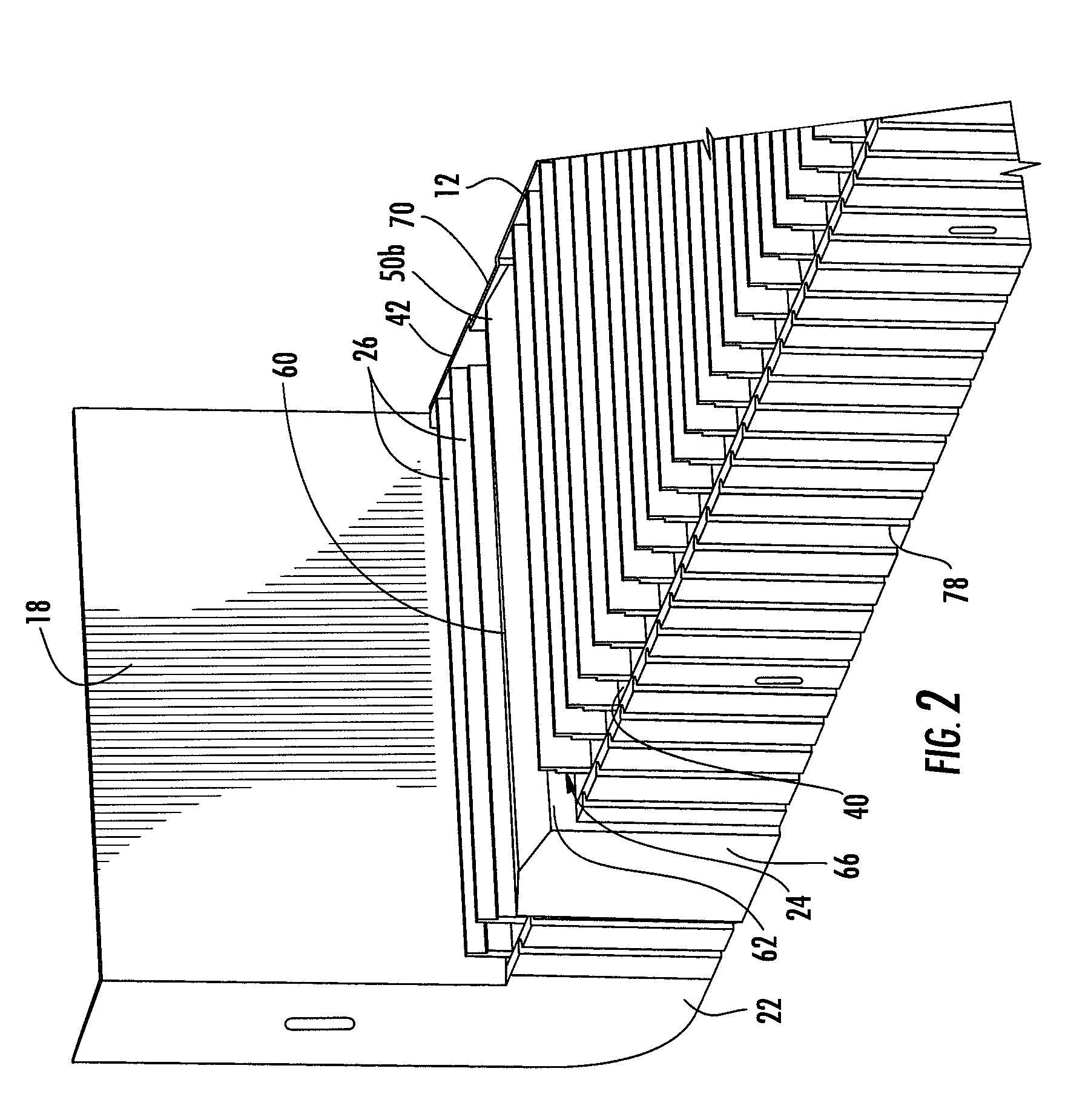
[0042]Referring to the drawings and, in particular, to FIG. 1, there is shown a sill flashing 10 according to one embodiment of the present invention. The sill flashing 10 is structured to be installed in an opening 110 in a wall 112 in connection with the installation of a window 114 (FIGS. 9-11) or other portal in the opening 110 so that the sill flashing 10 directs water out of the opening 110, e.g., to the outside of a building. Accordingly, the flashi...


PUM

PropertyMeasurementUnit
angleaaaaaaaaaa
lengthaaaaaaaaaa
sizeaaaaaaaaaa

Abstract

A sill flashing and method for installing a window or other portal in a wall opening are provided. The flashing includes a sill portion, at least one jamb portion at an angle relative to the sill portion, and a front face plate. The flashing is configured to be disposed in the opening with the sill portion disposed against a sill of the opening, an outer surface of the jamb portion disposed against one of the jambs of the opening, and a front face plate at an outer surface of the wall. The sill portion defines a plurality of support portions and a rear dam which can support the portal in the opening. The sill portion also includes one or more integral housing, configured to overlap an adjacent support portion when the flashing is cut and disposed multiple parts defining an interface therebetween.

Description

FIELD OF THE INVENTION[0001]This invention relates to the installation of windows, doors, or other building members and, more particularly, relates to a sill flashing for directing water out of an opening in a wall and preventing leakage of the water to the sill of the opening.BACKGROUND OF THE INVENTION[0002]During a typical installation of a window in a building, a rough opening is first prepared in a wall of the building for receiving the window. The rough opening is defined by two jambs that extend vertically from a head at the top of the rough opening to a sill at the bottom of the opening. In some cases, a weather resistant barrier material, such as a thin sheet of waterproof paper or plastic is disposed over the outer surface of the wall, and the barrier material is cut at the rough opening and folded into the opening. The barrier material forms a moisture barrier extending over the outer surface, but, due to the cuts, the barrier material does not normally provide a waterpro...

Claims


Application Information

Patent Timeline
Patent Type & Authority Patents(United States)
IPC IPC(8): E04D13/00E06B7/14E06B3/00E06B1/04E04D1/36E04B1/70
CPCE06B1/62Y10T29/51E06B2001/628E06B1/702
Inventor ALLEN, L. ROSS
Owner ALLEN L ROSS
Why Eureka
Try Eureka