
Unit arrangement

a unit arrangement and unit technology, applied in the direction of cooling fluid circulation, lighting and heating apparatus, domestic cooling apparatus, etc., can solve problems such as insufficient cooling power

Active Publication Date: 2010-08-17
RITTALWERK RUDOLF LOH GMBH & CO KG
View PDF4 Cites 10 Cited by
  • Summary
  • Abstract
  • Description
  • Claims
  • Application Information

AI Technical Summary

Benefits of technology

[0010]According to a preferred embodiment of this invention, the computing unit transmits to a control module a switch signal which corresponds to the temperature difference and the control module controls the cooling power of the cooling unit as a function of the switch signal. Regulation of the cooling power can thus be achieved in a simple manner if the control module controls the number of revolutions of at least one fan of the cooling unit as a function of the switch signal. Thus, the cooling power volume flow is increased, also the inlet temperature in the electrical unit can be maintained constant, if required.

Problems solved by technology

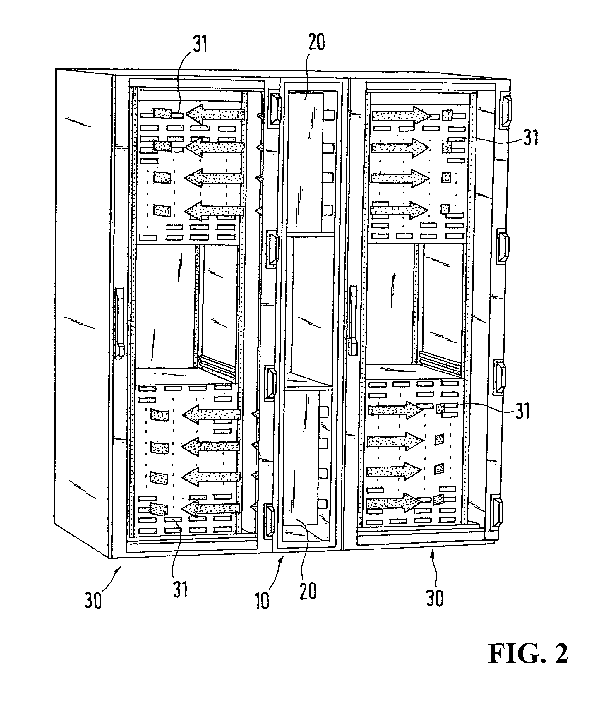
Correspondingly, the electrical units affect each other thermally and there is a danger of inadequate cooling power.

Method used


Image

  • Unit arrangement
  • Unit arrangement
  • Unit arrangement

Examples


Embodiment Construction

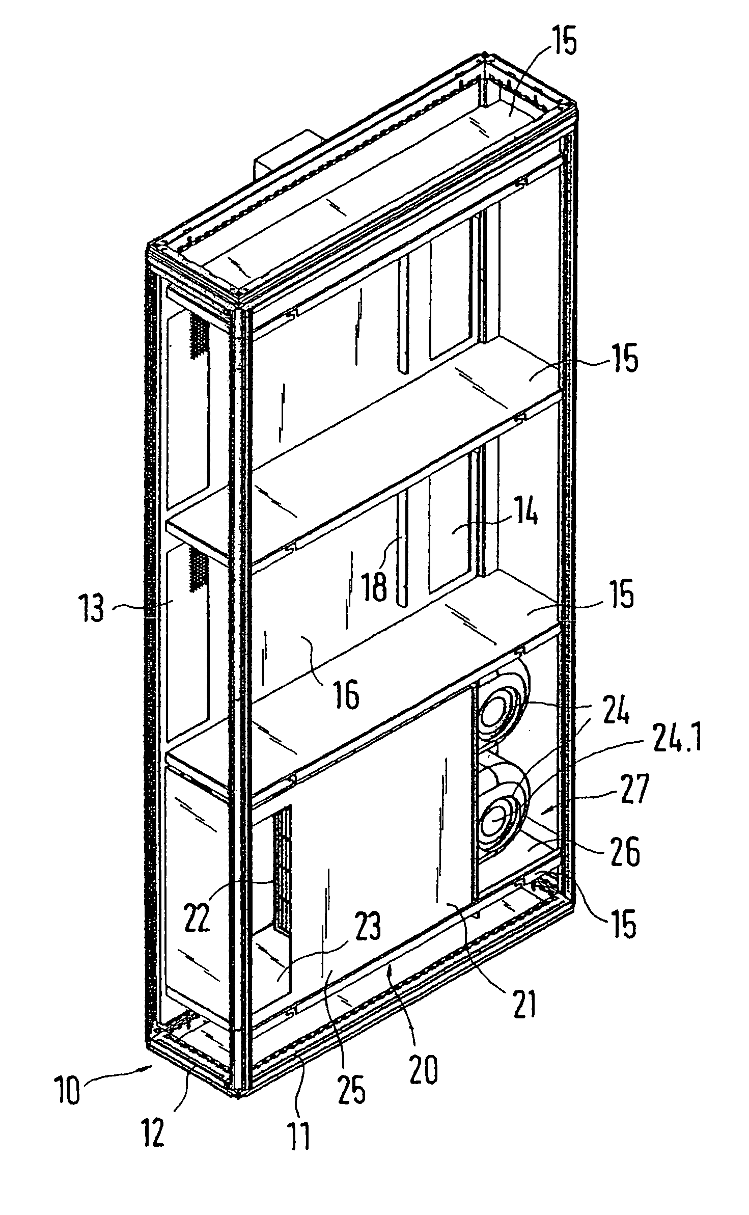
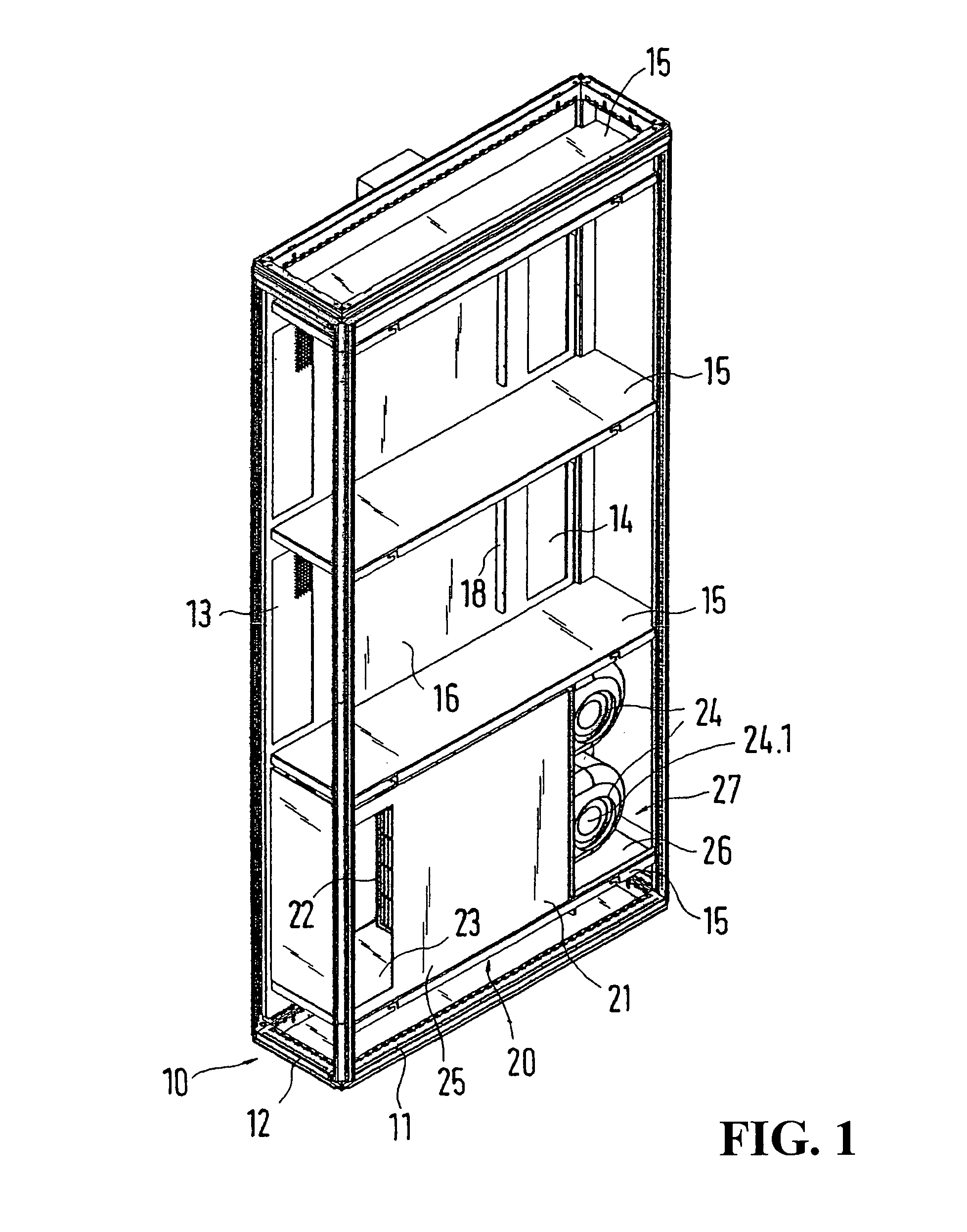
[0018]FIG. 1 shows a cooling unit 10 having a frame. This is assembled from twelve frame profiles 11, 12. The horizontal frame profiles 11, 12 form a base and a cover frame, in corner regions of which are welded the four vertical frame profiles which have identical cross-sections. The receiving chamber surrounded by the frame is subdivided into three partial receiving chambers by horizontal compartment bases 15. The partial receiving chambers can be covered on both sides on the frame broad sides by lateral covers 16. Each of the covers 16 has an air inlet 14 and a blower aperture 13. The front-side and rear-side narrow sides and also the roof side of the frame 15 are covered with suitable screens. The compartment bases 15 are fixed to the vertical frame profiles and receive one cooling module 20 respectively. Each cooling module 20 is assembled from two constructional units, a heat exchanger unit 21 and a fan unit 24.

[0019]The heat exchanger unit 21 has a heat exchanger housing 25, ...


PUM


Abstract

A unit arrangement having a receiving housing, in particular a switchgear cabinet, in an interior of which electrical units are accommodated and having a cooling device which is in air-conducting communication with the interior of the receiving housing via at least one air inlet and at least one blower aperture, and a cooling operation monitoring device. A requirement-orientated control of the cooling operation is possible when the cooling operation monitoring device has an inlet temperature sensor which measures a temperature of the air to be cooled which is supplied to the cooling unit via the air inlet. An outlet temperature sensor measures a temperature of the cooled air which is supplied to the interior of the receiving housing via the blower aperture. A computing unit of the cooling operation monitoring device determines a temperature difference between the temperature measured by the inlet temperature sensor and the outlet temperature sensor.

Description

BACKGROUND OF THE INVENTION[0001]1. Field of the Invention[0002]This invention relates to a unit arrangement having a receiving housing, particularly a switchgear cabinet, in the interior of which electrical units are accommodated and having a cooling unit which is in air-conducting communication with an interior of the receiving housing via at least one air inlet and at least one blower aperture, and a provided cooling operation monitoring device.[0003]2. Discussion of Related Art[0004]A unit arrangement is known from German Patent Reference DE 197 12 474. In this document, a cooling unit is described which can be mounted on a side wall of a switchgear cabinet. The side wall also has two through-openings. Through one of the through-openings, warm switchgear cabinet air is drawn in by a fan and supplied to a heat exchanger of the cooling unit.[0005]The cooled air can then be supplied again to the switchgear cabinet interior through the second through-opening. Control of the cooling ...

Claims


Application Information

Patent Timeline
Patent Type & Authority Patents(United States)
IPC IPC(8): F25D23/12
CPCH05K7/20572F25D17/00F25D19/00H02B1/565H05K7/20
Inventor DORRICH, MARTINNICOLAI, MICHAEL
Owner RITTALWERK RUDOLF LOH GMBH & CO KG
Learn More