Axial fan

A technology of axial flow and fan, applied in axial flow pumps, non-variable pumps, non-displacement pumps, etc., can solve the problems of efficiency reduction and achieve improved fan efficiency, reduced sound pressure level, and increased volume flow Effect

Active Publication Date: 2013-08-28
MAHLE INT GMBH
View PDF12 Cites 10 Cited by
  • Summary
  • Abstract
  • Description
  • Claims
  • Application Information

AI Technical Summary

Problems solved by technology

It has been found that due to this groove in the rear edge, a cross flow and / or a reverse flow of the flow of the fan blades results, which adversely affects the flow on the pressure side of the adjacent fan blades
As a result of the backflow and / or the transverse flow, vortex structures are generated in the region of the hub ramp, which leads to a reduction in efficiency

Method used


Image

  • Axial fan
  • Axial fan
  • Axial fan

Examples


Embodiment Construction

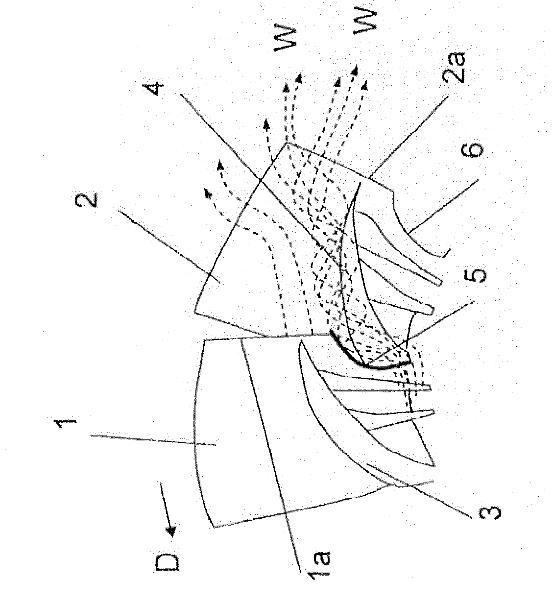
[0027] Fig. 1 shows the arrangement of fan blades 1, 2 of an axial fan according to the prior art. The direction of rotation of the fan is indicated by arrow D. The fan blades 1 , 2 each have a hub ramp 3 , 4 and a blade trailing edge 1 a , 2 a on their pressure side. The rear edges (or also called outlet edges) 1 a , 2 a each have a notch or groove 5 , 6 in their radially inner region (ie in the hub bevel 3 , 4 ). Such a recess and a reduction in the width of the fan blade is carried out in the prior art because on the one hand it means saving weight and on the other hand it is considered that the fan blade no longer provides a power gain in the area of ​​the blade root. However, crossflow and / or backflow have proven to be disadvantageous. The circulation through the blade trailing edge in the groove 5 produces a vortex trail indicated by the arrow W, which leads to a reduction in fan efficiency, a reduction in the volume flow and an increase in noise.

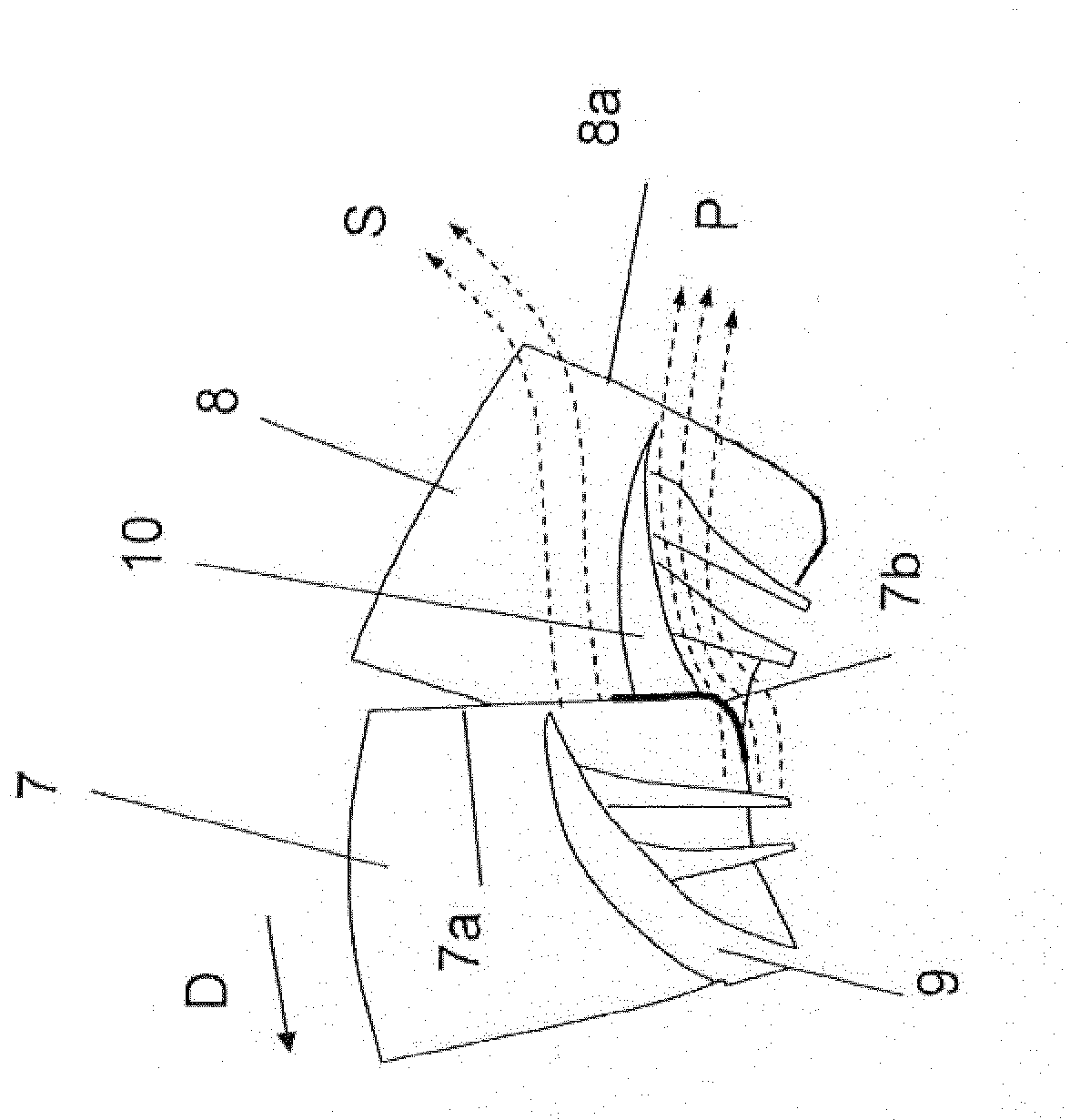
[0028] figure 2 A...


PUM


Abstract

The invention relates to an axial fan for delivering cooling air, in particular for an internal combustion engine of a motor vehicle, comprising fan blades (13, 14, 15) which are fastened to a hub (12) and which have a pressure side and a suction side and a trailing edge (16, 17, 18) and a blade depth (t), on the pressure side of which fan blades is arranged a hub ramp (13a, 14a, 15a) which rises counter to the direction of rotation (D) of the axial fan (11), wherein the trailing edge (16, 17, 18) has an outer region (16a, 17a, 18a) situated radially outside the hub ramp (13a, 14a, 15a) and has an inner region (16b, 17b, 18b) situated radially within the hub ramp (13a, 14a, 15a).

Description

technical field [0001] The invention relates to an axial fan for conveying cooling air, in particular for an internal combustion engine of a motor vehicle, according to the preamble of claim 1 . Background technique [0002] An axial fan of this type is disclosed in the applicant's previous patent application with official file registration number 102010042325.4. The axial fan has fan blades fastened to a hub ring, the fan blades have hub slopes on their pressure side and flow guide elements (also called stabilizers) on their suction side, which are used for affect the fan flow. The fan blades each have a front edge (ie the inlet edge) and a rear edge (ie the outlet edge). The rear edge of the fan blade has essentially two radially extending sections, namely an outer section arranged outside the hub bevel and an inner section arranged inside the hub bevel. For weight-saving reasons, the inner section of the rear edge is bent inwards, ie in the direction of the hub ring, s...

Claims


Application Information

Patent Timeline
Patent Type & Authority Applications(China)
IPC IPC(8): F04D29/32F04D25/02
CPCF04D25/022F04D29/329F04D25/02F04D29/32F04D19/002
Inventor 尤韦·阿舍曼尤韦·布拉斯弗雷德里克·吉尔博
Owner MAHLE INT GMBH
Why Eureka
Try Eureka