Assembly for cooling an exhaust gas stream

a technology for cooling and exhaust gas, which is applied in the direction of mechanical equipment, engine components, machines/engines, etc., can solve the problems of undesired increase in the back-pressure of exhaust gas in the exhaust gas system, objects or people, and possible hazard to nearby vehicle components, so as to prevent prevent overheating of the exhaust gas pipe. , the effect of preventing the release of exhaust gases

Inactive Publication Date: 2011-05-05
DEERE & CO
View PDF3 Cites 10 Cited by
  • Summary
  • Abstract
  • Description
  • Claims
  • Application Information

AI Technical Summary

Benefits of technology

[0014]Moreover, the fins may be arranged overlapping in the manner of a diaphragm in the circumferential direction of the outlet nozzle. The overlap reliably prevents an undesired release of exhaust gases in the region of the outlet nozzle.
[0015]Preferably, the exhaust gas pipe is surrounded at least in places by a touch guard. The touch guard takes the form in particular of a tubular cover, which is fitted along the outside of the exhaust gas pipe by means of a plurality of spacers. To prevent overheating of the exhaust gas pipe, the tubular cover may include a plurality of openings at least in the region of an exhaust tail pipe, which allow circulation of the air present between the exhaust gas pipe and the tubular cover.

Problems solved by technology

In so doing, the soot particles contained in the engine exhaust gas become deposited both on the surface of and also inside the filter wall, such that the exhaust gas back-pressure increases as the degree of clogging of the filter wall increases.
During the regeneration phases of the soot particle filter correspondingly high exhaust gas temperatures may occur at the exhaust tail pipe of the exhaust gas system, which may possibly constitute a hazard for nearby vehicle components, objects or people.
However, the shape of the nozzle or of the diverter housing, which shape tapers in the passage direction of the exhaust gas stream, leads to an undesired increase in the exhaust gas back-pressure in the exhaust gas system.
In this way, an undesired increase in the exhaust gas back-pressure may be restricted to the regeneration phases of the soot particle filter.

Method used


Image

  • Assembly for cooling an exhaust gas stream
  • Assembly for cooling an exhaust gas stream
  • Assembly for cooling an exhaust gas stream

Examples


Embodiment Construction

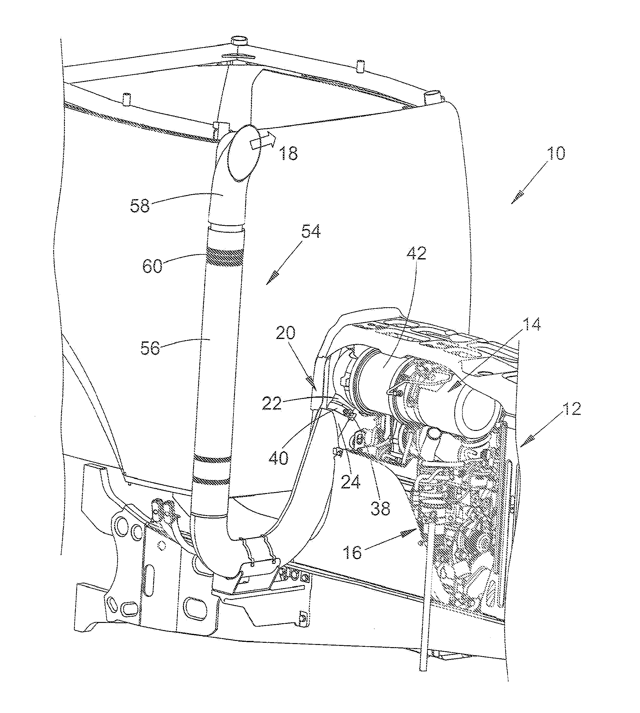
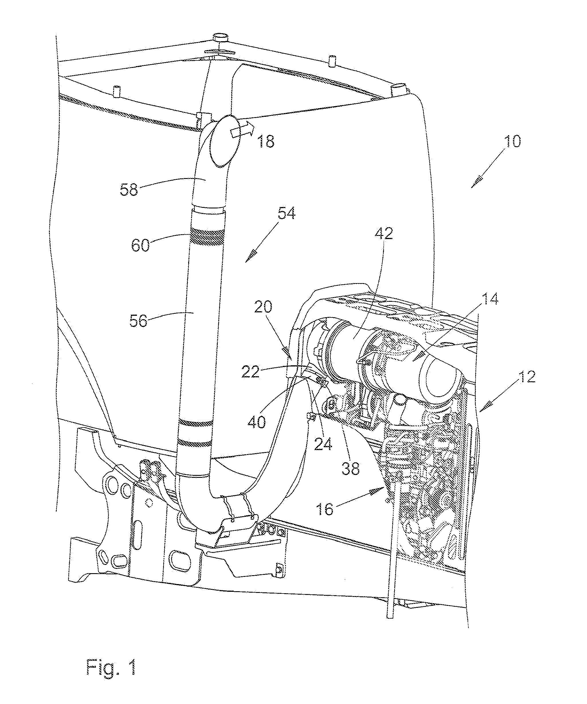
[0019]Referring to FIG. 1, an agricultural utility vehicle 10, such as a tractor, includes a soot particle filter 14 accommodated in an engine compartment 12. The soot particle filter is a conventional wall-flow filter. The exhaust gas produced by a diesel engine 16 of the vehicle 10 passes through a porous filter wall of a ceramic or metallic material. In the process, the soot particles contained in the engine exhaust gas become deposited both on the surface of and also inside the filter wall of the soot particle filter 14. Since the exhaust gas back-pressure increases as the degree of clogging of the filter wall increases, the deposited soot particles are burned at regular intervals to regenerate the soot particle filter 14, for which purpose the temperature of the engine exhaust gas is increased from time to time to temperatures of over 600° C. using an oxidation catalytic converter connected upstream of the soot particle filter 14.

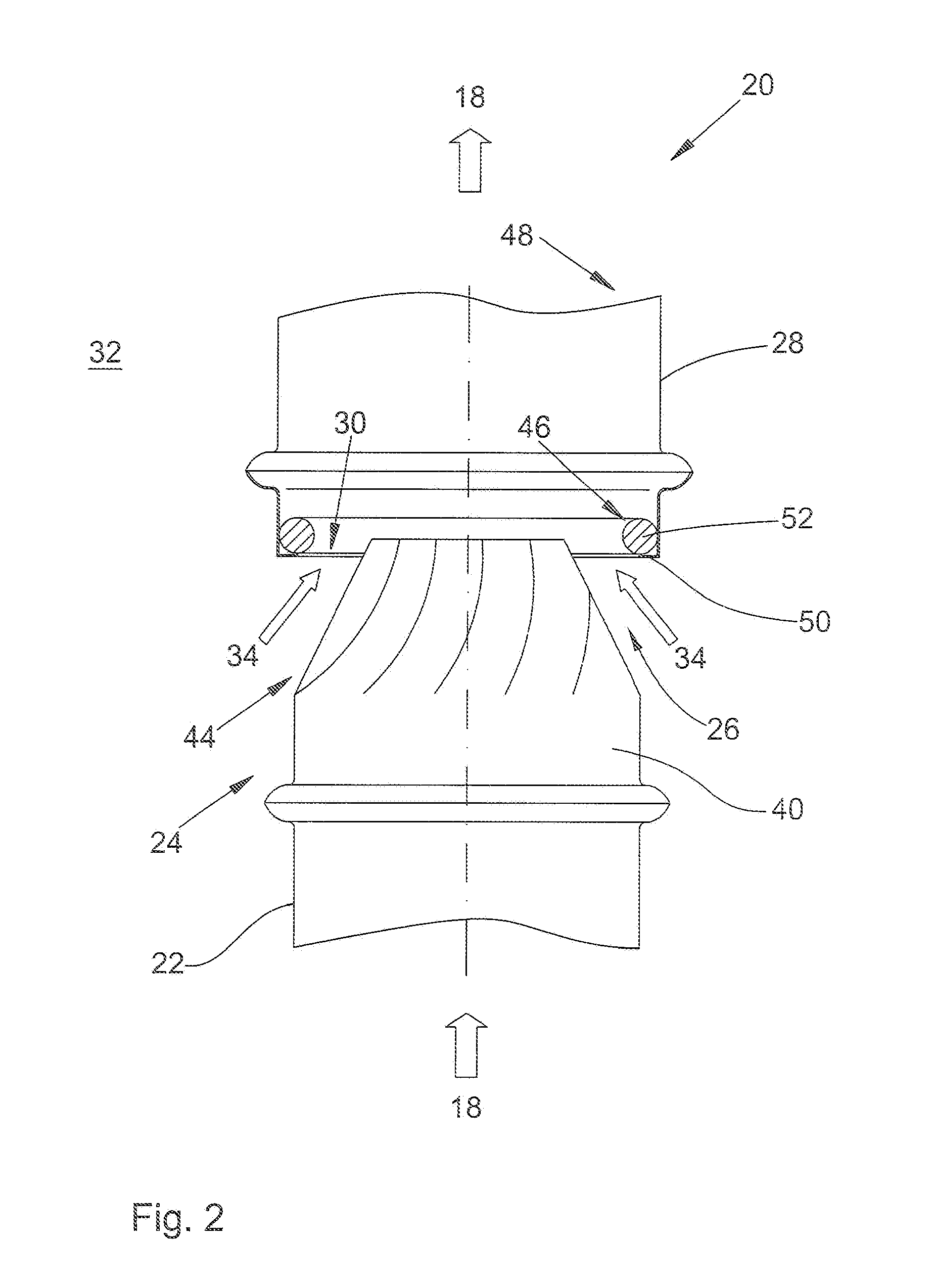
[0020]To cool the exhaust gas stream 18 emerging...


PUM


Abstract

An assembly for cooling an exhaust gas stream includes an outlet nozzle exposed to the exhaust gas stream. The outlet nozzle projects into an open end of an adjacent exhaust gas pipe so that a reduced pressure relative to the surrounding environment is produced in a suction region between the outlet nozzle and the exhaust gas pipe by flow of exhaust gas. Adjusting members vary the flow cross section of the outlet nozzle.

Description

FIELD OF THE INVENTION[0001]The present invention relates to an assembly for cooling an exhaust gas stream.BACKGROUND OF THE INVENTION[0002]The exhaust gas standards enacted by the European Union provide for a gradual reduction in the soot particles produced by diesel engines and discharged into the environment with the engine exhaust gas. Soot particle discharge is restricted by using soot particle filters, as a rule with “wall-flow filters”, in which the engine exhaust gas passes through a porous filter wall of a ceramic or metallic material. In so doing, the soot particles contained in the engine exhaust gas become deposited both on the surface of and also inside the filter wall, such that the exhaust gas back-pressure increases as the degree of clogging of the filter wall increases. To regenerate the soot particle filter, the deposited soot particles are therefore burned off at regular intervals, for which purpose the temperature of the engine exhaust gas is increased from time ...

Claims


Application Information

Patent Timeline
Patent Type & Authority Applications(United States)
IPC IPC(8): F01N5/02
CPCF01N13/082F01N2590/08F01N2270/02
Inventor LANG, MATTIASBRUNET, ROMAIN
Owner DEERE & CO
Why Eureka
Try Eureka